Injector Control Options
-
Delta
- LQFP112 - Up with the play
- Posts: 111
- Joined: Fri Jul 25, 2008 8:04 pm
- Location: Perth, WA, Australia
Re: Injector Control Options
If you could read the voltage across the 0.01ohm resistor under the protected FET that will help to determine the current going through the injector, and make sure its actually peak/holding with your injectors.

Re: Injector Control Options
Not to distract you folks to much, your doing some great work. But if we PWM the FET, there is a good chance we can significantly lower the power dissipated by the FET. Here's and example that was used with a DC motor.
http://www.picotech.com/applications/pw ... index.html
When the FET is in the transient state, it acts like a resistor. If you have a properly sized (or perhaps over sized) snubber cap, you can run the FET saturated, and the injector will be current limited. In this case it functions as a buck regulator with current feedback making it a current source.
I'd bet if we did it this way, we could get the power down from 60 watts to perhaps around 6 watts.
-
Delta
- LQFP112 - Up with the play
- Posts: 111
- Joined: Fri Jul 25, 2008 8:04 pm
- Location: Perth, WA, Australia
Re: Injector Control Options
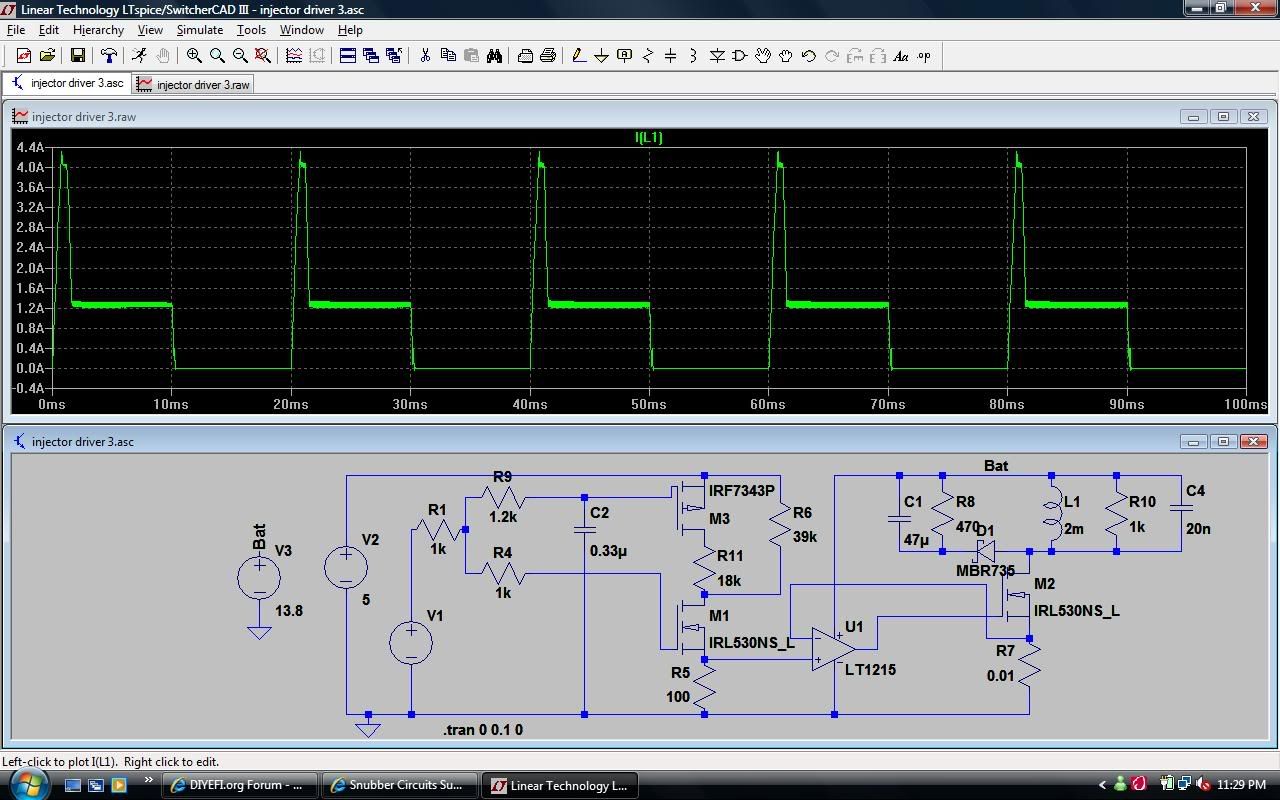
That was my original design to use PWM from software for peak/hold and on off for saturated. But Fred indicated he didn't really want to do pwm in software so I came up with this instead - technically this IS pulsed - if you stick the circuit in a spice simulator the mosfet is being driven above and below its switching threshold quickly, so it IS actually tuning on and off quickly - it just doesn't require special software to do it - and isn't going all the way to 0V and all the way up to 5V. I suppose I should actually calculate the REAL power dissipation rather than looking at the peaks and making an educated guess. If the software PWM frequency is reasonably similar to the frequency being generated by the opamp feedback circuit you could use the mosfet directly with the same snubber network and cut out the dual mosfet a few resistors the opamp etc.
Re: Injector Control Options
Great it sounds like the power draw may be lower then the expected 60 watts. Do you know what frequency(ies) it uses? The frequency will help determine how much time is spent in the transient zone, therefor we can predict the power dissipated
Re: Injector Control Options
Back on pg 6 it appears Delta's picture went away. Perhaps it was moved or renamed? I was trying to find it and take a look at it because it's the more revised version. Any chances it can come back?

Re: Injector Control Options
I cached it here :
http://i260.photobucket.com/albums/ii15 ... 3vkiet.jpg
As for software PWM, it's a horrendous waste of pins when there are other solutions available that achieve the same thing. Also, that is exactly what B&G do and would be asking for a law suit.
Those were my two main gripes. I forget what else I said at the time, I may have had other points too.
Cheers,
Fred.
DIYEFI.org - where Open Source means Open Source, and Free means Freedom
FreeEMS.org - the open source engine management system
FreeEMS dev diary and its comments thread and my turbo truck!
n00bs, do NOT PM or email tech questions! Use the forum!
The ever growing list of FreeEMS success stories!
FreeEMS.org - the open source engine management system
FreeEMS dev diary and its comments thread and my turbo truck!
n00bs, do NOT PM or email tech questions! Use the forum!
The ever growing list of FreeEMS success stories!
Re: Injector Control Options
I agree software PWM for that task is a waste. Better to do that in hardware and free up the resources for something useful. It can't cost more then a couple pennies for a VCO, attached to a sense resistor and your done. Spending the couple pennies will make for a much more stable design and reliable design.
Note linear sells many buck chips and has many app notes available. I'd bet we can find one for current regulation.
Note linear sells many buck chips and has many app notes available. I'd bet we can find one for current regulation.

Re: Injector Control Options
Pictures forthcomming, with actual numbers. Measured across 0.01 ohm resistor, and across the injector, as well as the input signal. I saw constant noise, no idea why. regular, though. Hard to say with the MS.
I used the "coil test" mode to get a 5V signal square wave.
I didn't see a heck of a lot of current limiting. In fact, I didn't see the current I expected. At ~12.3V battery, and 1.5 ohm of total resistance at the terminal block), I was getting 60 mv across the resistor - about 6 amps.
Later, I was able to see current limiting, but it was a small amount. Oh, and the resistor gets nice and toasty. I can touch it, but it's unpleasant. Will post pics soon.
Re: Injector Control Options
Pics, still little explanation:
First setup, chn 1 across resistor, chn 2 input signal:

Same as above, one less injector in parallel (~2.6 ohms)

Later, reading chn1 across resistor, chn2 across injector:

Curious noise hooked up as above, "no signal"

Pulses closer together:

ZOOOMED!

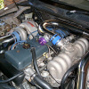
Where I took my signals:

(Er, from positive rail to injector ground)
Somehow me drunk playing with fire

First setup, chn 1 across resistor, chn 2 input signal:
Same as above, one less injector in parallel (~2.6 ohms)
Later, reading chn1 across resistor, chn2 across injector:
Curious noise hooked up as above, "no signal"
Pulses closer together:
ZOOOMED!
Where I took my signals:
(Er, from positive rail to injector ground)
Somehow me drunk playing with fire
Re: Injector Control Options
Oh, interestingly - there's a star-ground inside the cab! The "signal" ground and the "chasis" ground are all stuck together, 6 pins in this connector are all shorted by the cap.

The cap

Lastly, miatas without the head, and with the ground to the body chopped off... don't have ground going to the ECU. Yanking on the wires might somehow move the head... cause it works intermittentedly.
The cap
Lastly, miatas without the head, and with the ground to the body chopped off... don't have ground going to the ECU. Yanking on the wires might somehow move the head... cause it works intermittentedly.