DFH - Defacto FreeEMS Hardware in KICAD
Re: freeEMS_1.0 rev A KICAD
It doesn't hurt to have lots of spare ground pads, plus a few 5V and one or two 12V pads spare for unforeseen use. You can never have too many, especially on the first PCB.

Re: freeEMS_1.0 rev A KICAD
Here's freeEMS 1.0 A.16 now with P.01
Release notes and files can be found here
https://sourceforge.net/project/showfil ... _id=623459
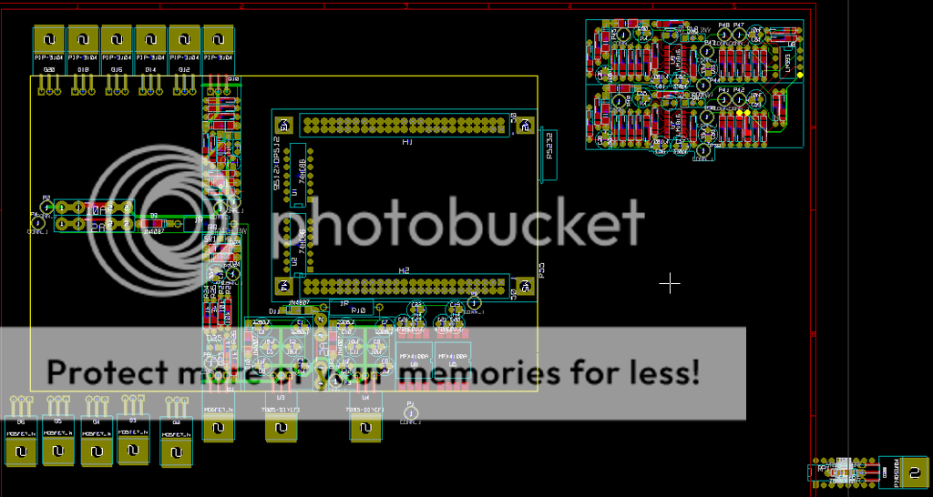
Big things here, I've added the RPM PCB layouts, and MAP layouts. The RPM circuits are off the board at the moment, haven't decided where or exactly, they just barely fit under the TA card. It's getting tight, but most components are now placed at least close to where they should be.
Here's a snap shot of the PCB.
Release notes and files can be found here
https://sourceforge.net/project/showfil ... _id=623459
Big things here, I've added the RPM PCB layouts, and MAP layouts. The RPM circuits are off the board at the moment, haven't decided where or exactly, they just barely fit under the TA card. It's getting tight, but most components are now placed at least close to where they should be.
Here's a snap shot of the PCB.

Re: freeEMS_1.0 rev A KICAD
JH: Wow, that's really coming along. I wish there was something useful I could do...
If the OEM's can have a connector, so can we. We can be intelligent about it, but if you can't build an EMS with a connector on it, you can't build an EMS!
I'm slowly becoming a fan of the little wire blocks Jean uses. A connector wouldn't bother me a ton, and the screw terminals would be a step up, but ANYTHING that lets you unhook the board is a good thing. Soldering the computer to the car is pretty much a bad idea.Fred wrote:They don't have to be particularly fat, but yes, a pair of wires up to the board. The power and ground pins should be left N/C on all boards. The other stuff would be plug in, but a reliable permanent installation would hard wire those too.
If the OEM's can have a connector, so can we. We can be intelligent about it, but if you can't build an EMS with a connector on it, you can't build an EMS!

Re: freeEMS_1.0 rev A KICAD
Thanks for turning the card around!
Flacid, I guess what could be done is pull the header off the card and put a socker for two pins on the board and a pair of pins hanging down from the header holes. That should work pretty well and be semi reliable.
I can't say I like the solder thing either, but have a think about what other options there are... Screws WILL wiggle loose sooner or later, esp if you tin the wires.
For testing/setup you could just run a plug and short lead as I do now, but once installing it in the car for good, a solder joint could be the best option.
Fred.
DIYEFI.org - where Open Source means Open Source, and Free means Freedom
FreeEMS.org - the open source engine management system
FreeEMS dev diary and its comments thread and my turbo truck!
n00bs, do NOT PM or email tech questions! Use the forum!
The ever growing list of FreeEMS success stories!
FreeEMS.org - the open source engine management system
FreeEMS dev diary and its comments thread and my turbo truck!
n00bs, do NOT PM or email tech questions! Use the forum!
The ever growing list of FreeEMS success stories!
Re: freeEMS_1.0 rev A KICAD
Ah but there is. You could make the connection card. Or you could start picking my layout appart.8InchesFlacid wrote:I wish there was something useful I could do...
My plans are for the signals to leave at misc points. Those points will need to be routed to the edge of the board and attached to a connector of some sort. I know a handful of people have expressed interest in having the wires leave freeEMS via connector, so that is probably the best and easiest first card to make. I've seen many ATV's and such that use harness connectors instead of a PCB connector and my app is small engine related, so I'm planning on leaving that as an option. Perhaps this connector board could be called "freeEMS 1.0 connector" or if you have a name, to recommend go for it. One think to keep in mind, I'm fairly sure the connector will be incorperated in the card that includes boost, IAC, and the other common stuff, that is beyond the bare min. I don't think a connector has been decided on, and I'm quite certain the symbol and footprint don't exist for it at this point in time. I'd say that's probably a good place to jump in. Pick one and go. Nice features in the connector include snap connections so you know you have full pin penatration, one pin connection per trace (no multi ground pins because one pin can't handle the current crap), water tight option, and low cost.
If you start picking appart my layout, don't hold back. Of course there are unfinished traces, but much can be ironed out, double checked, ect. For example, I've only made some very basic guesses at the current flow and voltage(s) in the traces. Right now it may or may not burn a trace, or jump to another trace. Basic practice tells me it's probably OK, but I haven't picked it appart yet to confirm.
Little wire blocks? Are you refering to Jim Stim? I'm also guessing you're not talking about the termainl blocks.8InchesFlacid wrote:I'm slowly becoming a fan of the little wire blocks Jean uses.
Re: freeEMS_1.0 rev A KICAD
Don't get too carried away, I still need to finalise the pin outs for you on a few things... Sorry I'm taking so long, real life is getting in the way at the moment, and for the foreseeable future too :-(
DIYEFI.org - where Open Source means Open Source, and Free means Freedom
FreeEMS.org - the open source engine management system
FreeEMS dev diary and its comments thread and my turbo truck!
n00bs, do NOT PM or email tech questions! Use the forum!
The ever growing list of FreeEMS success stories!
FreeEMS.org - the open source engine management system
FreeEMS dev diary and its comments thread and my turbo truck!
n00bs, do NOT PM or email tech questions! Use the forum!
The ever growing list of FreeEMS success stories!
Re: freeEMS_1.0 rev A KICAD
Ah, ok, so you're saying make a board that biascally takes all the various wires, and brings them together to a single output. Sure, and I could make that pick up all the odds and ends, serial ports, etc.
I'd be happy if there were a few plugs on it. General IO, Power, Serial (though a decent USB adapter like what I have really works pretty well), etc.
Given that my OEM ecu uses 3 regular "pins", I'm sure I could get something, even like an RC car battery "T" connector, it should handle all the power no problem. KISS.
Re: freeEMS_1.0 rev A KICAD
I'm not so worried about the pin-outs right now, those are fairly easy to push around, drawing several wires or creating several label names is a bit of a pain. Also creating symbols and footprints is a bit of work as well.
Also I don't see why we can't have multiple connector options on one connector PCB. If you're looking for low cost and high Z, the DB connector could work for you. If your looking for water tight and cost is less of a concern, then a fancy shmancy AMP might be up your alley. A connector board could have both, and you populate the connector you want. Thoughts?
Also I don't see why we can't have multiple connector options on one connector PCB. If you're looking for low cost and high Z, the DB connector could work for you. If your looking for water tight and cost is less of a concern, then a fancy shmancy AMP might be up your alley. A connector board could have both, and you populate the connector you want. Thoughts?

Re: freeEMS_1.0 rev A KICAD
I doubt very much you'll be able to fit the footprint of different connectors in the same location without some interference. Moreover, even if it is possible you'll have a hard time routing the needed traces.
If many connectors are desired I think that the best option is to simply have many board variants. Not the best thing when having the boards made but certainly the best thing from a design and reliability point of view.
On a 2 layer board with a single connector footprint it's hard enough to have access to all the pins on some connectors if you have some big traces for high current that you don't want additional holes all over the place.
Jean
Re: freeEMS_1.0 rev A KICAD
The only thing that leaps out to me there is having different connectors on different sides. Heck, you could populate both if you wanted. Depends how much box vs board space we have. In a pinch you could use it for diagnostics.
If you were exceedingly clever, you could probably use one connector to bring signals in (soldered wires to the main board) and one to bring them out via the connector.
With the exception of the few bits of circuitry (jump them in?) which actually modify signals, I'm sure you could do both of those.