
OK, I thought lm2940 has that, but it doesn't so the diode should stay I think. Harmless addition anyway and standard practice isn't it?8InchesFlacid wrote:Oh, ok, the diode makes sense, then. Just have to find out if it's needed, though I would probably still leave the hole in the board just in case someone buys a lamer LDO?
DFH - Defacto FreeEMS Hardware in KICAD
Re: freeEMS_1.0 rev A KICAD
DIYEFI.org - where Open Source means Open Source, and Free means Freedom
FreeEMS.org - the open source engine management system
FreeEMS dev diary and its comments thread and my turbo truck!
n00bs, do NOT PM or email tech questions! Use the forum!
The ever growing list of FreeEMS success stories!
FreeEMS.org - the open source engine management system
FreeEMS dev diary and its comments thread and my turbo truck!
n00bs, do NOT PM or email tech questions! Use the forum!
The ever growing list of FreeEMS success stories!

Re: freeEMS_1.0 rev A KICAD
It's standard on the Freeems if we leave it in. 
____________
JHarvey:
Can we get the input circuit I have added in. I think it's significantly better (and just as simple) as some of the other voltage followers. I'd like to know what format you want it in - single copy of the circuit, two in one sheet, etc etc. I am not yet very familiar with the who heiriarcical thing, but am willing to learn. Comment here or in the hall-effect input thread:
http://www.diyefi.org/forum/viewtopic.p ... 412&p=4528

Re: freeEMS_1.0 rev A KICAD
Here's freeEMS 1.0 A.15 now with P.01
Release notes and files can be found here
https://sourceforge.net/project/showfil ... _id=623102
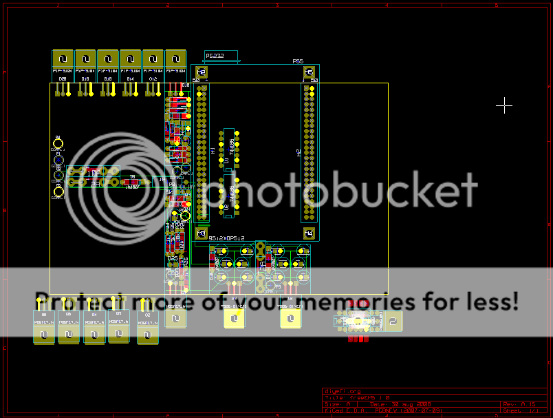
Big things here, I've included the hall buffer op amp, I've created a draft PCB layout with 1 injector and 1 ignition driver 2 reg's and a basic layout for the rest of the board. I'm waiting for review before I move forward with coping these drivers to the following 5 locations. I plan on placing the maps, and other components in the mean time.
Here's a snap shot of the PCB rev controled by P.01 at the end of the schematic rev.
Release notes and files can be found here
https://sourceforge.net/project/showfil ... _id=623102
Big things here, I've included the hall buffer op amp, I've created a draft PCB layout with 1 injector and 1 ignition driver 2 reg's and a basic layout for the rest of the board. I'm waiting for review before I move forward with coping these drivers to the following 5 locations. I plan on placing the maps, and other components in the mean time.
Here's a snap shot of the PCB rev controled by P.01 at the end of the schematic rev.
Re: freeEMS_1.0 rev A KICAD
Done :-)
Is there any good reason why the db9 can't hang off the end of the board? It's not a big deal to run a ribbon for it, but it's a lot easier to not have to. Especially if you plan to pull it out and plug into a test rig.
Good work.
Is there any good reason why the db9 can't hang off the end of the board? It's not a big deal to run a ribbon for it, but it's a lot easier to not have to. Especially if you plan to pull it out and plug into a test rig.
Good work.
DIYEFI.org - where Open Source means Open Source, and Free means Freedom
FreeEMS.org - the open source engine management system
FreeEMS dev diary and its comments thread and my turbo truck!
n00bs, do NOT PM or email tech questions! Use the forum!
The ever growing list of FreeEMS success stories!
FreeEMS.org - the open source engine management system
FreeEMS dev diary and its comments thread and my turbo truck!
n00bs, do NOT PM or email tech questions! Use the forum!
The ever growing list of FreeEMS success stories!
Re: freeEMS_1.0 rev A KICAD
I just turned it 90cw and moved it to the edge of the board. I like it better that way, don't have to run between the pins to get traces across. I might have to push is to the top right, but right now it's slightly above the center line. The DB9 is hanging off the right edge, power comes from the left.
Re: freeEMS_1.0 rev A KICAD
If bright yellow means connected, then there is something else we need to discuss.
I think power should come in on the two pin header (solder or plug) and not through the 50 pin connectors as the trace paths and sizes don't seem appropriate there. Without doing that I could not get noise free operation. This was so bad with ribbon cables that the digital waves were affected too.
Fred.
DIYEFI.org - where Open Source means Open Source, and Free means Freedom
FreeEMS.org - the open source engine management system
FreeEMS dev diary and its comments thread and my turbo truck!
n00bs, do NOT PM or email tech questions! Use the forum!
The ever growing list of FreeEMS success stories!
FreeEMS.org - the open source engine management system
FreeEMS dev diary and its comments thread and my turbo truck!
n00bs, do NOT PM or email tech questions! Use the forum!
The ever growing list of FreeEMS success stories!
Re: freeEMS_1.0 rev A KICAD
In the above, it appears I had the "highlight net" selecting the ground net. You might also notice the green and red is bright colored as well. My game plan is to have grounds and powers sized and to have conductive paths to the power pins. Then to flood any remaining reasonable area with a non conductive ground (including a path round the outside edge of the board. I haven't sized the power traces yet, I plan on over sizing them by 2X so if I expect 5 amps, I'll size them for 10 amps. I've included 2 ground points, that leave the PCB and I'm planning / hoping people will include 2/3 wires of varying length's perhaps one that connects to the engine, and two that go where ever.
I'm also working on the theory that there will be a connector board, that will get the traces to a connector at the edge of the board.
I'm also working on the theory that there will be a connector board, that will get the traces to a connector at the edge of the board.
Re: freeEMS_1.0 rev A KICAD
I think maybe you misunderstand (either that or I do). The power shouldn't go into the CPU card through the 50 pin headers at all. Same with CAN, same with bdm, same with serial. Doing so will create noise issues based on the CPU's own power requirements and switching loads.
DIYEFI.org - where Open Source means Open Source, and Free means Freedom
FreeEMS.org - the open source engine management system
FreeEMS dev diary and its comments thread and my turbo truck!
n00bs, do NOT PM or email tech questions! Use the forum!
The ever growing list of FreeEMS success stories!
FreeEMS.org - the open source engine management system
FreeEMS dev diary and its comments thread and my turbo truck!
n00bs, do NOT PM or email tech questions! Use the forum!
The ever growing list of FreeEMS success stories!
Re: freeEMS_1.0 rev A KICAD
Gotcha now. What should we do, run a fat wire up to the TA board? I believe BDM, 232, ect will be their own interfaces anyhow. Not the normal hardwired stuff. Only the power it hardwired. Right?
Re: freeEMS_1.0 rev A KICAD
They don't have to be particularly fat, but yes, a pair of wires up to the board. The power and ground pins should be left N/C on all boards. The other stuff would be plug in, but a reliable permanent installation would hard wire those too.
DIYEFI.org - where Open Source means Open Source, and Free means Freedom
FreeEMS.org - the open source engine management system
FreeEMS dev diary and its comments thread and my turbo truck!
n00bs, do NOT PM or email tech questions! Use the forum!
The ever growing list of FreeEMS success stories!
FreeEMS.org - the open source engine management system
FreeEMS dev diary and its comments thread and my turbo truck!
n00bs, do NOT PM or email tech questions! Use the forum!
The ever growing list of FreeEMS success stories!