I will try and summarize the following discussion by keeping this first post up-to-date editing it every once in a while.
The idea:
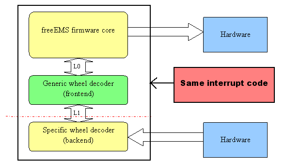
To have common wheel decoder and scheduler (CWDS) code and multiple plug-ins for various combinations of crank/cam wheels and methods for their decoding and scheduling. The CWDS should NOT be aware of any specifics of a particular wheel combination and is there to prevent or reduce code duplication.
The specific wheel plug-in substitution is strongly considered to be in form of compile-time, source file substitution, that corresponds to the desired wheel combination. All such plug-in files will have a common structure of entry points, in accord to the interface between the CWDS and the plug-in.
Good starting point on this interface definition is to abstract away all that is common to any wheel decoder/scheduler.
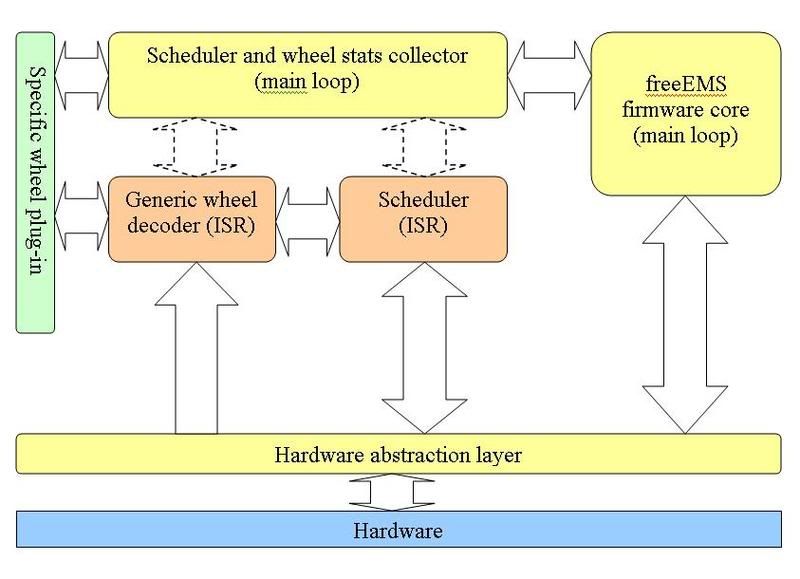
Proposed architecture diagram from wheel decoder stand-point: (sorry for the crap quality - work in progress)

Diagram legend:
Yellow blocks: regular firmware component
Red blocks: time critical interrupt handling component
Green blocks: substitutable plug-in component
Blue blocks: hardware
Solid arrow: direct intercomponent interface
Dashed arrow: indirect synchronized interface
Blocks description:
Generic wheel decoder (ISR): Handles tach interrupts. Uses the specific wheel info/methods (from the plug-in) to establish the crank/cam position. Invokes the Scheduler (ISR) to schedule the "off-tooth" events.
Scheduler (ISR):
Schedules the "off-tooth" events (sets up timer interrupts). Handles event timer interrupts. Executes (or initiates the execution of) the events (i.e ign or inj).
Watch this space for summary of the components and interfaces in the above diagram...
Further ideas on tach input verification:
As discussed on other threads, it would be very desirable to verify tach signals coming from crank/cam wheels before making important decisions/actions (spark, inj, etc..) based on those signals.
It would be a sin not to use in tach verification such important info as the effect of rotational inertia (physical model), factors that may accelerate the crank/cam wheels (IC engine model) and the particular teeth configuration of the specific wheels.
to be continued...
