My bad, I had both injector and ignition data sheets open. I grabbed the wrong number. The injector sheet had the same test setup, but as you note, that's not what you had in mind.Fred wrote:Nope, no such part in fig 17. No point looking at the other diagrams either as it's an ignition driver and they are test setups anyway.it shows .01 ohm as a shunt resistor.
I don't think this is really a big deal. The current sense .01 resistor is as simple as adding to blank pads on the PCB. Those that aren't looking for this capability, will simply solder an old lead across it making it a 0 resistor. I'm sure that with the first go at it, we'll want the ability to look at that signal.Fred wrote:I'm hoping that you don't try and do thatIf we're going to hope for current sense in the first freeEMS boardFor non P&H injectors we don't want or need the extra complication.
Hall sensors that run saturated produce nice square waves that are good for different pickups. Hall sensors don't need to be run saturated, and can produce analog signals based on the amount of flux that is crossing them. Putting a hall sensor on a trace will allow you to measure the flux, which coincides with the current running in that trace.Fred wrote:Less complicated than what? Hall sensors interface directly with the CPU (via basic diode/resistor/capacitor protection and filtering) and live in the engine bay, not on the board. For Hall, not a lot needs to be done, for VR we need a conditioner, but that doesn't belong in this thread.then I should probably recommend we add space for a hall sensor. Much less complicated hardware wise and costs about the same dollar wise.
A prepackaged version can be found here. http://www.allegromicro.com/en/Products ... sensor.asp However, if you calibrate it yourself, you can same some good cash, by using a much cheaper hall sensor.
I've started playing with QUCS to look at some injector parameters. I tried to attach the files, but it didn't work. Said board quota has been reached. Probably better for these spice files to go to the CVS instead.

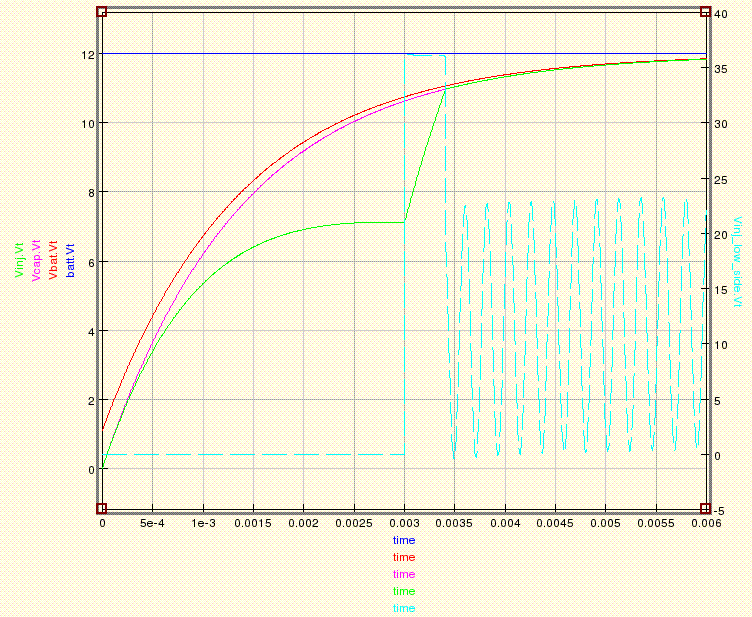
This graph shows some ringing problems caused by a tank circuit. This is one of the reasons why shunting the inductive current is important. Also note the diode causes the 3ms to 3.5ms issue. Oh the diode, perhaps I should post the schematic.

I used a switch for now rather then a FET or IGBT to keep it simple. I also simulated the reverse diode with the Dclamp diode, it's set at 36v reverse bias. I choose 25mF to match the 25mH of the inductor because it felt like that would balance out. As you can see that doesn't matter much. It still rings significantly.
Other notes I expect the injector resistance due to the wire length to be about 15 ohms. That resistance is mixed with the inductance, so I split it and put it on both sides of the inductor to simulate a more real world inductor. It would probably be better if there were several inductors and resistors, but this should work OK for now.
Rbat = internal resistance of a battery, calculated by 240 cold cranking amps with 12V.
Rcap = randomly picked to include resistance due to wire and cap plates.
Cballance = cap that helps with the inrush current when you open the injector.
Rinj = half the injector DC resistance
R1 = the other half of the resistance, oops should have renamed.
L2 = the injector inductance
Some parameters I'm looking to learn, what is the typical period and duty cycle of the injectors? Have those kinds of parameters been determined yet? I'm also assuming it's a fixed period.


