
I believe there is only one semi larger change, most changes are fairly small at this point. The regulators could generate less heat, and be a bit more robust than the linear reg's we have in there. I've drafted the new regulator(s), and put it up in github. I'm hoping I can get some feed back. I'll try to make it better tomorrow, like adding the enable line that Marcos had in there, ect, but it's mostly drafted at this point.
https://github.com/jharvey/puma_JAH
Puma board for FreeEMS

Re: Puma board for FreeEMS
I have one in my hand that has four smd style mounting feet, the 5 tiny pins across the back, and two little plastic bumps to locate it into some holes/vias/something below it. I don't know where it came from/part numbers/etc but I can find out. I'll post pics when I have completed installing it all.
DIYEFI.org - where Open Source means Open Source, and Free means Freedom
FreeEMS.org - the open source engine management system
FreeEMS dev diary and its comments thread and my turbo truck!
n00bs, do NOT PM or email tech questions! Use the forum!
The ever growing list of FreeEMS success stories!
FreeEMS.org - the open source engine management system
FreeEMS dev diary and its comments thread and my turbo truck!
n00bs, do NOT PM or email tech questions! Use the forum!
The ever growing list of FreeEMS success stories!
Re: Puma board for FreeEMS
Considering that we are now in the tagged and qc/bug fix stage, I'd like to see all changes be as minor as possible, and all changes be heavily peer reviewed prior to being incorporated into the design.jharvey wrote:I believe there is only one semi larger change, most changes are fairly small at this point. The regulators could generate less heat, and be a bit more robust than the linear reg's we have in there. I've drafted the new regulator(s), and put it up in github. I'm hoping I can get some feed back. I'll try to make it better tomorrow, like adding the enable line that Marcos had in there, ect, but it's mostly drafted at this point.
https://github.com/jharvey/puma_JAH
I want to see a comprehensive change set list before Spin 2 goes ahead, with justifications, reasons, side effects, etc for everything. The idea is to go only forward and not have any regressions. To hit the target of world class quality, in the shortest possible space of time. If there aren't actual issues found with the reg/power supply, why change it at this critical stablisation stage? Check out the way Debian releases work, that's what we're emulating (or trying to) here, and something all designers/developers should aim for.
Changing the entire power supply for the CPU says to me "full retest" as it's a fairly critical subcircuit. Is that really a good idea unless there is actually a real problem with the existing stuff? IE, changes between spin 1 and 2 should be fixes, and minor easy improvements, not major improvements/redesigns. I would suggest waiting till Puma version 2 or something before making it generally better. That way we can focus on, and be much more SURE of, Puma 1 being as stable and performant as possible.
Does any of this make sense to anyone but me? :-/
Fred.
DIYEFI.org - where Open Source means Open Source, and Free means Freedom
FreeEMS.org - the open source engine management system
FreeEMS dev diary and its comments thread and my turbo truck!
n00bs, do NOT PM or email tech questions! Use the forum!
The ever growing list of FreeEMS success stories!
FreeEMS.org - the open source engine management system
FreeEMS dev diary and its comments thread and my turbo truck!
n00bs, do NOT PM or email tech questions! Use the forum!
The ever growing list of FreeEMS success stories!
-
nitrousnrg

- LQFP144 - On Top Of The Game
- Posts: 468
- Joined: Tue Jun 24, 2008 5:31 pm
Re: Puma board for FreeEMS
Good to see it on github! I can copy your stuff or merge it, its your call.
About the connector, seems good. The fact that it is TH isn't a big thing. The actual trough hole USB connector is *really* weak if it doesn't have his lateral support leads soldered to the board.
Also, I'm not a big fan of having 3 regulators. We have to do something with the linear one, its not shutdown-able, and too big for the things it has to supply. I can see it isn't connected to other circuitry, maybe the plan is to ditch it. Maybe those milliamperes can be provided from a zener (its under 35mA, but imposing a limit like that could be counterproductive if a user wants to draw more current from that supply).
I have no experience with those regulators, but it doesn't seem like a good idea to have them supplying the analog circuitry. However, its mostly a prejudice, if it is ok, we should go for it, its a good thing to move towards switching supplies, the MCU regulator is running too hot. Your regulators needs more space, although that isn't a problem, at least in that region of the pcb. The inductor is bulky, but can be placed somewhere :-)
In case you already have worked with those regulators... do you have some recommendations/notes about them?
Its too late, but while surfing the net I stumbled upon a dual regulator:
http://focus.ti.com/lit/ds/symlink/tps54386.pdf
And Fred, you can feel how hot the MCU reg is running. That SOT package is beautiful, but I won't put in the market a product with that kind of behavior. Yes, it runs, but not in the way I expect. It can be a painful change, but i'm fine as long as it doesn't compromise my 3 spin plan :-).
The solution for the high temperature is a bigger linear regulator attached to a heatsink, or a non-linear regulator. I'm already thinking on changes for a puma 2 (tiger?), but they aren't close to reality.
We still have to narrow down the reset issue, my next board will use a big regulator instead of the actual SMD, just to test if the behavior is the same. I've put many 47uF capacitors in many places, but the mcu still doesn't start. Nevertheless, a single 1000uF between VDD and ground makes it start just fine (by default it has only a 22uF tantalum, plus a bunch of 0.1uF).
Btw, the transistor footprints for the injector drivers are all wrong. I would be in peace with myself if there were only 4 puma boards, but that is not the actual situation.
Finally, I'm finding out that kicad developers frequently use text editors over the .brd file to make bulk changes. Its just to let people know.
Marcos
Re: Puma board for FreeEMS
plus one, its pathetic.nitrousnrg wrote:The actual trough hole USB connector is *really* weak if it doesn't have his lateral support leads soldered to the board.
Hell no, we need two because of the shutdown/startup/sleep behaviour we want, but we do not need more than two, IMO. If not for the sleep thing, we'd definitely use only one.Also, I'm not a big fan of having 3 regulators.
not shutdownable? doesn't the shutdown come from the fact that the key removes power from the second reg? As for being too big, no such thing. Besides, to220 on the edge takes up minimal room and keeps heat out of the PCB.We have to do something with the linear one, its not shutdown-able, and too big for the things it has to supply.
Yuck, hell no!!Maybe those milliamperes can be provided from a zener (its under 35mA, but imposing a limit like that could be counterproductive if a user wants to draw more current from that supply).
I have the same prejudices, and so do others. Plus, switching supplies are VERY layout sensitive, and induce NOISE in an environment where we are already fighting to NOT have noise. I'm not a fan, despite their advantages.I have no experience with those regulators, but it doesn't seem like a good idea to have them supplying the analog circuitry. However, its mostly a prejudice
Mine isn't, yet, but it's declocked to 16mhz at the moment, so that's why, probably. I told you guys that it draws a lot. And it will draw more with xgate running in future too.And Fred, you can feel how hot the MCU reg is running. That SOT package is beautiful, but I won't put in the market a product with that kind of behavior. Yes, it runs, but not in the way I expect.
BIG PLUS ONE!!!The solution for the high temperature is a bigger linear regulator attached to a heatsink
To be clear, it starts, but it doesn't load the user code, which simply means that the voltage comparison is not OK between the load/run pin, and the internal reference. I'm looking at mine now, and I do not see the VDD caps, are these something that I need to add on? There are FAR less caps on this thing than the TA card, I think that's worth noting. They have 16uF 10V caps on various CPU pins, We probably should too. Where can I hook those up, Marcos? If you tell me that it's impossible now, I may fly there to injure you with a rusty tea spoon. Post in my comments thread please. I need mine to be working by end of tomorrow so that I can start installing it and taking readings/testing code.We still have to narrow down the reset issue, my next board will use a big regulator instead of the actual SMD, just to test if the behavior is the same. I've put many 47uF capacitors in many places, but the mcu still doesn't start. Nevertheless, a single 1000uF between VDD and ground makes it start just fine (by default it has only a 22uF tantalum, plus a bunch of 0.1uF).
Don't panic, yet. The use of them for FETs is fine, and maybe you can jumper things around and cut traces to make the P&H stuff work too, or find a different darlington that works/fits.Btw, the transistor footprints for the injector drivers are all wrong. I would be in peace with myself if there were only 4 puma boards, but that is not the actual situation.
Fred.
DIYEFI.org - where Open Source means Open Source, and Free means Freedom
FreeEMS.org - the open source engine management system
FreeEMS dev diary and its comments thread and my turbo truck!
n00bs, do NOT PM or email tech questions! Use the forum!
The ever growing list of FreeEMS success stories!
FreeEMS.org - the open source engine management system
FreeEMS dev diary and its comments thread and my turbo truck!
n00bs, do NOT PM or email tech questions! Use the forum!
The ever growing list of FreeEMS success stories!
-
nitrousnrg
- LQFP144 - On Top Of The Game
- Posts: 468
- Joined: Tue Jun 24, 2008 5:31 pm
Re: Puma board for FreeEMS
I think you still don't get how that circuit works. The MCU and the other 5v circuits (ie, both regulators) are powered from the same 12v wire, it saves one wire in the wiring harness. The ON/OFF information lies in the big, fat 12v power wire. The little shutdown circuit enables or not the regulator in function of the voltage present in the power 12v cable. Anyway, you can solder the cable from the key directly to the regulator, there are free pads in there. The bridge (white wire probably) I put in your board could cut and connected to the key.Fred wrote:not shutdownable? doesn't the shutdown come from the fact that the key removes power from the second reg? As for being too big, no such thing. Besides, to220 on the edge takes up minimal room and keeps heat out of the PCB.We have to do something with the linear one, its not shutdown-able, and too big for the things it has to supply.
Still, I want to hear jharvey's experience. I like the efficiency of a switching supply, specially temperature-wise.Fred wrote:I have the same prejudices, and so do others. Plus, switching supplies are VERY layout sensitive, and induce NOISE in an environment where we are already fighting to NOT have noise. I'm not a fan, despite their advantages.I have no experience with those regulators, but it doesn't seem like a good idea to have them supplying the analog circuitry. However, its mostly a prejudice
I filled the board with 47uF (and a 229uF) caps, in parallel with some of the 0,1uF capacitors of the MCU. 5 caps in total, it doesn't work until i put the big 1000uf cap.Fred wrote:To be clear, it starts, but it doesn't load the user code, which simply means that the voltage comparison is not OK between the load/run pin, and the internal reference. I'm looking at mine now, and I do not see the VDD caps, are these something that I need to add on? There are FAR less caps on this thing than the TA card, I think that's worth noting. They have 16uF 10V caps on various CPU pins, We probably should too. Where can I hook those up, Marcos? If you tell me that it's impossible now, I may fly there to injure you with a rusty tea spoon. Post in my comments thread please. I need mine to be working by end of tomorrow so that I can start installing it and taking readings/testing code.We still have to narrow down the reset issue, my next board will use a big regulator instead of the actual SMD, just to test if the behavior is the same. I've put many 47uF capacitors in many places, but the mcu still doesn't start. Nevertheless, a single 1000uF between VDD and ground makes it start just fine (by default it has only a 22uF tantalum, plus a bunch of 0.1uF).
I'd move on. If changing the reg doensn't fix this, I don't know whats going on. A simple delay to the reset pin will make the cpu to start correctly, its an acceptable solution, at least for this week. There are bigger things going on.
Marcos
Re: Puma board for FreeEMS
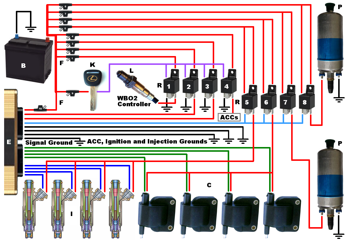
This is unacceptable. Four separate 12V feeds need to enter through the loom, always-on clean, switched clean, switched dirty, reference. The reference is missing from the diagram as it is a signal, not part of the power wiring, however maybe it should be added. There should be NO big fat power cables on the board (except possibly snubber/spike catching dump for low z drivers), but there SHOULD be a big fat ground cable. In fact, the power cable SHOULD be small and shitty. There is no amount of clever design that gets away from the basic voltage divider network that your power and ground wires form. Thus the ground should be low resistance/impedance to keep the ECU V ref ground close to zero at all times, and the power should be weak so that any current drops most of the voltage across this wire. The functionality to provide or not provide power to key-on-only parts exists in the key and/or relay OUTSIDE the box, this is part of the vehicle wiring setup that goes with any installation. Saving a wire in the loom is the worst excuse I've ever heard for adding parts and complexity... This old diagram is THE way FreeEMS boxes get wired up. The "how to wire up your freeems" documents will be standard across all variants because the power and ground stuff is definitely going to be part of the hardware compliance doc. There is far too much opportunity to fuck things up and get it all wrong like MegaSquirt and I don't want my name on shit that is not done right. See diagram designed in consultation with the community and agreed on by all:nitrousnrg wrote:I think you still don't get how that circuit works. The MCU and the other 5v circuits (ie, both regulators) are powered from the same 12v wire, it saves one wire in the wiring harness. The ON/OFF information lies in the big, fat 12v power wire. The little shutdown circuit enables or not the regulator in function of the voltage present in the power 12v cable.Fred wrote:not shutdownable? doesn't the shutdown come from the fact that the key removes power from the second reg? As for being too big, no such thing. Besides, to220 on the edge takes up minimal room and keeps heat out of the PCB.We have to do something with the linear one, its not shutdown-able, and too big for the things it has to supply.
http://i260.photobucket.com/albums/ii15 ... iring5.png
Aside from that, I looked at the schematic earlier too, but didn't comment yet, however now is a good time. Your switching network is no good either, it has a v drop and wont function during cranking under extreme conditions. Combined with the diode, dropping 1.2v is unacceptable. that brings total drop up to around 2v and therefore min bat v up to 7v, which is on the high side.
I guess none of this is anything the connector board can't take proper care of.
Sure, I wasn't saying he shouldn't tell us what he thinks, I was just telling you what I think and know...Still, I want to hear jharvey's experience. I like the efficiency of a switching supply, specially temperature-wise.Fred wrote:I have the same prejudices, and so do others. Plus, switching supplies are VERY layout sensitive, and induce NOISE in an environment where we are already fighting to NOT have noise. I'm not a fan, despite their advantages.I have no experience with those regulators, but it doesn't seem like a good idea to have them supplying the analog circuitry. However, its mostly a prejudice
I posted in my thread too,. but for the record, my board/regs are dead cold sitting running code at 40mhz. There is no temperature problem on mine, does yours have something wrong with it? How hot are we talking? maybe a solder bridge somewhere? or something more weird? As far as I can tell your design (which I don't like with the smd reg...) works perfectly well and does not need changing.
It's not only an acceptable solution (put a tant in the design for this, 10V, 2.2uF did you say?), it's also best practice. If there is induced noise on the reset line, the MCU, will, funnily enough, reset, which is bad when you're driving along... A certain crappy EMS that I have on my truck for the next 2 days does this due to insufficient reset pin protection/filtering. It would just be nice if it behaved itself without that, but if you're loaded the **** out of it with caps and it only behaves with an enormous amount, then that's not a good solution. Have you scoped the rise profile of the voltage to see how quickly it comes up? How about fed it with a gruntier reg to see if that makes it come up correctly? Is it coming up too fast or too slow that is the issue? In any case, mine ran code in NZ for the first time an hour and half ago or so, so congrats on having a running board in two countries now :-)I filled the board with 47uF (and a 229uF) caps, in parallel with some of the 0,1uF capacitors of the MCU. 5 caps in total, it doesn't work until i put the big 1000uf cap.
I'd move on. If changing the reg doensn't fix this, I don't know whats going on. A simple delay to the reset pin will make the cpu to start correctly, its an acceptable solution, at least for this week.
I wish I'd paid more attention to this thread earlier, a lot of shit would have been avoided :-/ Anyway, onwards and upwards! :-)
Fred.
DIYEFI.org - where Open Source means Open Source, and Free means Freedom
FreeEMS.org - the open source engine management system
FreeEMS dev diary and its comments thread and my turbo truck!
n00bs, do NOT PM or email tech questions! Use the forum!
The ever growing list of FreeEMS success stories!
FreeEMS.org - the open source engine management system
FreeEMS dev diary and its comments thread and my turbo truck!
n00bs, do NOT PM or email tech questions! Use the forum!
The ever growing list of FreeEMS success stories!
Re: Puma board for FreeEMS
That USB connector is a very common style. I was a bit less interested in it, as the SMT means your physical strength is only as good as the coper glue. I would like the style that incorporates thru hole. Hmmm, perhaps a hybrid footprint would work. SMT pads that have solder that flows through the board should be fairly strong as well, and you can save $.50 by using that smt style. Does yours have gold plated contacts?Fred wrote:I have one in my hand that has four smd style mounting feet, the 5 tiny pins across the back, and two little plastic bumps to locate it into some holes/vias/something below it. I don't know where it came from/part numbers/etc but I can find out. I'll post pics when I have completed installing it all.
Re: Puma board for FreeEMS
There is a list, I just updated it in git. See the file "spin2 improvements". It's not quite what you are requesting, it's more of a check list for Marcos and I to use such that we can verify the items we brought up have been addressed.Fred wrote:I want to see a comprehensive change set list before Spin 2 goes ahead, with justifications, reasons, side effects, etc for everything.
The drafted switch reg circuit is the one I drafted in the 5554 design based on input from movex. This reg circuit used 5V and 3.3V. It was built and tested on a running engine, so it should be OK for starting conditions. I don't have hands experience with it, however movex does. I changed it slightly to make it 5v and 5v. I should probably get rid of that linear 3rd supply, but haven't gotten around to deleting it yet. I do have experience with other buck/boost switching supplies, and basically the input and output caps filter the noise issues such that they aren't a problem.
Switching back to the old regulator circuit is fairly easy, the schematic still exist, simply make some changes on the top level drawing and your schematic is back. I don't think there is much need to do a full retest. I'd say if you get your 5V and it's ripple is lower than the current reg, it's as good or better than the original drafted design. I'd be very happy to hear a review on it.
Re: Puma board for FreeEMS
You have an excellent point, I ripped a pad off today with what I thought was minor force :-/ I have to fix it tomorrow...jharvey wrote:That USB connector is a very common style. I was a bit less interested in it, as the SMT means your physical strength is only as good as the coper glue.
I have it in my hand, but the lighting is somewhat yellow, so I can't positively say. I'll have a look in sunlight tomorrow and make a call :-) EDIT, I just took some macro photos and I would say that they are not gold plated.Does yours have gold plated contacts?
Re the second post, there are two aspects to the design, the schematic/circuit design, and the pcb layout/design. Both things need testing/thought, however while a change to a schematic sub section usually doesn't affect much else in the design and is easy to isolate/analyse, that is not true of the pcb layout. The PCB layout, if changed, can easily have mistakes that affect nearby things in unpredictable ways. Hence my cautious approach.
The general idea is to freeze a design for future release and then make minimal conservative and careful changes to it such that the risk of a regression is minimised. This is a software practice, but applies almost as well to hw design like this. I mean, if you change enough stuff, you're basically back at square one with regards to making sure everything works AND works together.
Excuse me if I'm touchy on this, but sloppy release management and strategy or lack thereof is a big problem in software and doing it right makes a HUGE difference to reliability and consistency and ultimately happy customers/users.
DIYEFI.org - where Open Source means Open Source, and Free means Freedom
FreeEMS.org - the open source engine management system
FreeEMS dev diary and its comments thread and my turbo truck!
n00bs, do NOT PM or email tech questions! Use the forum!
The ever growing list of FreeEMS success stories!
FreeEMS.org - the open source engine management system
FreeEMS dev diary and its comments thread and my turbo truck!
n00bs, do NOT PM or email tech questions! Use the forum!
The ever growing list of FreeEMS success stories!