Wheel decoder/scheduler architecture

Official FreeEMS vanilla firmware development, the heart and soul of the system!
User avatar
ababkin
LQFP112 - Up with the play
Posts: 215
Joined: Tue Jan 15, 2008 5:14 pm

Wheel decoder/scheduler architecture

Post by ababkin »

Let's start the discussion about this here.
I will try and summarize the following discussion by keeping this first post up-to-date editing it every once in a while.


The idea:
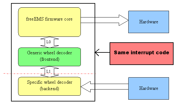
To have common wheel decoder and scheduler (CWDS) code and multiple plug-ins for various combinations of crank/cam wheels and methods for their decoding and scheduling. The CWDS should NOT be aware of any specifics of a particular wheel combination and is there to prevent or reduce code duplication.
The specific wheel plug-in substitution is strongly considered to be in form of compile-time, source file substitution, that corresponds to the desired wheel combination. All such plug-in files will have a common structure of entry points, in accord to the interface between the CWDS and the plug-in.

Good starting point on this interface definition is to abstract away all that is common to any wheel decoder/scheduler.


Proposed architecture diagram from wheel decoder stand-point: (sorry for the crap quality - work in progress)
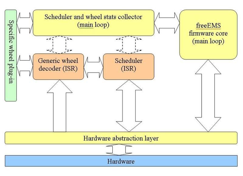
Image
Diagram legend:
Yellow blocks: regular firmware component
Red blocks: time critical interrupt handling component
Green blocks: substitutable plug-in component
Blue blocks: hardware

Solid arrow: direct intercomponent interface
Dashed arrow: indirect synchronized interface


Blocks description:

Generic wheel decoder (ISR): Handles tach interrupts. Uses the specific wheel info/methods (from the plug-in) to establish the crank/cam position. Invokes the Scheduler (ISR) to schedule the "off-tooth" events.

Scheduler (ISR):
Schedules the "off-tooth" events (sets up timer interrupts). Handles event timer interrupts. Executes (or initiates the execution of) the events (i.e ign or inj).


Watch this space for summary of the components and interfaces in the above diagram...


Further ideas on tach input verification:

As discussed on other threads, it would be very desirable to verify tach signals coming from crank/cam wheels before making important decisions/actions (spark, inj, etc..) based on those signals.
It would be a sin not to use in tach verification such important info as the effect of rotational inertia (physical model), factors that may accelerate the crank/cam wheels (IC engine model) and the particular teeth configuration of the specific wheels.

to be continued...
Last edited by ababkin on Sun Mar 02, 2008 2:28 am, edited 5 times in total.
Legal disclaimer for all my posts: I'm not responsible for anything, you are responsible for everything. This is an open and free world with no strings attached.
User avatar
AbeFM
Post Whore!
Posts: 629
Joined: Sat Feb 16, 2008 12:11 am
Location: Sunny San Diego
Contact:

Re: Wheel decoder front/backend interface definition

Post by AbeFM »

You would incorperate more... 'statusy' variables in the middle section? So, the backend does not decide if a signal is valid, is the motor is fully synced (for sequential opperation), or just crank synced (good for batch firing when starting or 'lost')? I have a feeling there's low(er) speed stuff that will need to be decided somewhere, things just like that. Defining the engine "state" is tricky, but important for knowing what to do when you let someone like me build the hardware. :-) Certainly avoiding huge disasters is a good idea.

Not sure if this is thread-appropriate, but I'm definately curious. Any more ideas about what's done where and why, I'd love to see.
User avatar
Fred
Moderator
Posts: 15431
Joined: Tue Jan 15, 2008 2:31 pm
Location: Home sweet home!
Contact:

Re: Wheel decoder front/backend interface definition

Post by Fred »

Here's the issue :

EDIT : There was a matching diagram to this, but now that its gone, it feels a bit naked. I still feel that its close to accurate though.
Image

The green bit is just a set of state variables etc.

More input will come in from the left of course and the rest of the "core firmware code" ticking away in the background.

heres how it will likely work :

interrupt occurs

code to read signal runs
-> look at current state
-> calculate new state
-> update state

code to act on information relevant from previous code runs
-> schedule injector events based on config and state
-> schedule ignition events based on config and state

interrupt returns

because these chunks of code will likely be some of the most complex in the whole system, GCC will (rightly so) refuse to inline them. Thus they need to be local code. The first version that does Denso mode for example (by the way, I got approval to test on the good womans car last night) should be written such that the second part of the code does not need to be touched for most signal implementations.

However, if someone wants to hack dizzy mode in (assuming we don't do it etc) they can gut the entire file, and as long as they only interact through the same variables, the rest of the code should stand alone and untouched.

So, one function, two distinct and independent blocks of code inside it that run sequentially, read first, write/schedule second. But in the same file (unfortunately, by physical requirement).

Admin.
DIYEFI.org - where Open Source means Open Source, and Free means Freedom
FreeEMS.org - the open source engine management system
FreeEMS dev diary and its comments thread and my turbo truck!
n00bs, do NOT PM or email tech questions! Use the forum!
The ever growing list of FreeEMS success stories!
User avatar
Fred
Moderator
Posts: 15431
Joined: Tue Jan 15, 2008 2:31 pm
Location: Home sweet home!
Contact:

Re: Wheel decoder front/backend interface definition

Post by Fred »

Additionally, that diagram is actually upside down from a time order perspective, also, totally OT : http://burnallgifs.org/
DIYEFI.org - where Open Source means Open Source, and Free means Freedom
FreeEMS.org - the open source engine management system
FreeEMS dev diary and its comments thread and my turbo truck!
n00bs, do NOT PM or email tech questions! Use the forum!
The ever growing list of FreeEMS success stories!
User avatar
ababkin
LQFP112 - Up with the play
Posts: 215
Joined: Tue Jan 15, 2008 5:14 pm

Re: Wheel decoder front/backend interface definition

Post by ababkin »

I am happy to see your feedback guys

The diagram was an attempt to illustrate a very high level abstract architecture diagram. It does NOT represent data flow or sequence of events (this needs different type of diagrams), just the main components and connections/interfaces between them.

Comments on Fred's diagram suggestion:
- i doubt it's a good idea to have the backend (or even front end) be hardware aware. IMO, there should be a layer that would be responsible for interfacing the hardware to the whole of freeEms firmware. One of the big advantages of having this layer would be an easily configurable IO, i.e binding logical IO to the physical IO. Example: the firmware will operate with such concepts as crank tach, cam tach, coil #1, 2, 3...; injector #1, 2..., instead of setting/reading port registers directly. This will be important as i envision that freeEMS will have as many custom hardware configurations as there will be the number of users.

In addition, i'd encourage everyone contributing to not limit yourselves to talking about specific implementation details (not talking specifics here, just the proper way of doing things), but try and keep an open mind, this will help avoiding restricting yourself to only one way of skinning a cat.
Remember: implementation details should flow out of an abstract specification/design, not the other way around.


Alex
Legal disclaimer for all my posts: I'm not responsible for anything, you are responsible for everything. This is an open and free world with no strings attached.
User avatar
Fred
Moderator
Posts: 15431
Joined: Tue Jan 15, 2008 2:31 pm
Location: Home sweet home!
Contact:

Re: Wheel decoder front/backend interface definition

Post by Fred »

Heres the thing, that code only performs two functions, read wheel, produce output, both are highly dependent on the style of the wheel(s) and both MUST live inside the capture ISR(s).

It would be nice if it was split into two parts that interracted through some specific well defined data set, however, by nature of the random shapes of all the ****ed up oem wheels, that both of those sections of code must know about the shape, the hardware pins involved will ALWAYS be the same ones, and any unused by a particular configuration will be available for other functions to use through some sort of port register etc.

Other than the state between phases, you have input configuration that the code needs to read that should be always the same, and you have output data that the code needs to complete which will always be the same too.

Provided a "wheel module" works properly with its wheel under all dynamic conditions, reads the same config (such that config is the same for all codes) and outputs the same data (such that the same data is available for all codes, what is inside it is unimportant provided it is fast.

This code is going to be highly time critical and MUST be efficient. layer after layer of crap that might obscure the actual intent function, and implications is just as bad, if not WORSE than hacky asm/low C that is poorly docced and highly optimised.

None of the acres of other code to do all the accessory stuff listed in our long feature wishlist needs to know about or get involved with that wheel/inject/ignite code at all.

NOTE : I have NOT described any implementation detail at all except that that is required by definition of our hardware, i.e. it all lives inside the two ISR's with some minor accessory/cleanup/followup/etc code in the interrupts that actually fire the injectors and coils.

These are the interrupts :

Action/schedule (the code we are discussing) :
IC0 : crank/rpm/position
IC1 : cam/flag(s)


Cleanup (what happens to run as a result of what is "planned" by the other two) :
OC2 : injector 1
OC3 : injector 2
OC4 : injector 3
OC5 : injector 4
OC6 : injector 5
OC7 : injector 6
PIT1 : Dwell start
PIT2 : Dwell end/coil fire
PIT3 : Staged injection start

The config stuff that these pieces of code need are things like cylinder count, port count, coil count, etc either in raw form, configure on the fly, or preconfigured form based on start up time and init.c. Additionally, If we do our fuel/ign calcs on the fly, we need access to all basic config and tuning data to do that, as well as the staging, rpm limit config etc and anything else that affects normal "make the engine run" operation in any way.

Because interrupts are stand alone blocks of code anyway, there isn't much you can do to layer/modularise etc. You are stuck with just this : KISS and document well

The KISS part is why I am SO keen to steer clear of special case code.

To summarise, 4 parts :
inter chunk comms variables (sync, etc)
config/tuning data (ve, cyl count, etc)
read wheel(s)
configure out timer(s)

Does that help you see the big picture?

Fred.
DIYEFI.org - where Open Source means Open Source, and Free means Freedom
FreeEMS.org - the open source engine management system
FreeEMS dev diary and its comments thread and my turbo truck!
n00bs, do NOT PM or email tech questions! Use the forum!
The ever growing list of FreeEMS success stories!
User avatar
Fred
Moderator
Posts: 15431
Joined: Tue Jan 15, 2008 2:31 pm
Location: Home sweet home!
Contact:

Re: Wheel decoder front/backend interface definition

Post by Fred »

Also, what IS a backend if it is not low level "get it done" code?
DIYEFI.org - where Open Source means Open Source, and Free means Freedom
FreeEMS.org - the open source engine management system
FreeEMS dev diary and its comments thread and my turbo truck!
n00bs, do NOT PM or email tech questions! Use the forum!
The ever growing list of FreeEMS success stories!
User avatar
ababkin
LQFP112 - Up with the play
Posts: 215
Joined: Tue Jan 15, 2008 5:14 pm

Re: Wheel decoder front/backend interface definition

Post by ababkin »

Admin wrote:Also, what IS a backend if it is not low level "get it done" code?
Perhaps backend was not the best term for this. 'Plug-in' would have been better i think.
It is a code that brings a particular flavour to 'getting it done' ;)
In fact, it doesn't even have to be functional code - could be just a big data structure, speaking in implementation lingo, which could also be uploaded just like any other user specified parameters. This would, for example, have an advantage of not having to recompile for diff wheel configs.
That's exactly why i don't want us to preclude ourselves and set in stone that it has to be 'code' in a 'file', cause it doesn't have to be.

I also understand the harm of having extra overhead, esp in a real-time embedded application. We just have to find ways to reduce it while keeping the codebase maintainable and easy to understand not through documenting every single line of code, but by documenting the whole system hierarchically: Architecture/interface diagrams, data flow diagrams, execution vs time diagrams, usage cases, requirement docs, etc. Then documenting each block individually in detail.

I know, a tall order, but that is my ultimately designed and built EMS. Oh and i don't mind documenting the bulk of it.
Legal disclaimer for all my posts: I'm not responsible for anything, you are responsible for everything. This is an open and free world with no strings attached.
User avatar
Fred
Moderator
Posts: 15431
Joined: Tue Jan 15, 2008 2:31 pm
Location: Home sweet home!
Contact:

Re: Wheel decoder front/backend interface definition

Post by Fred »

ababkin wrote:In fact, it doesn't even have to be functional code - could be just a big data structure, speaking in implementation lingo, which could also be uploaded just like any other user specified parameters. This would, for example, have an advantage of not having to recompile for diff wheel configs.
That would be optimal for sure, and I would love to see it like that, and if at all possible, yes, that is the way we will go about it. I'm struggling to see how this can be done in an optimal way though. i.e. high performance implementation for a given obscure wheel with 19 teeth on one side and 5 oddly spaced on the other or some such monstrosity.
That's exactly why i don't want us to preclude ourselves and set in stone that it has to be 'code' in a 'file', cause it doesn't have to be.
I sure hope you are right!
We just have to find ways to reduce it while keeping the codebase maintainable and easy to understand not through documenting every single line of code
The same (rather talented) guy that I've seen abstract things to the point of incomprehensibility because you can't see what it's actually doing refers to such comments as "A bad smell", so, wherever possible, the code will self document based on well chosen variable and function names. A simple line before each structure (if/loop/case/etc) stating what it does overall is a good idea, then reading the code should tell you how it does it with no further information. I would like most source files to contain a decent sized comment at the top that explains in pseudo code what the code below does in fairly good detail as a readable structure. I want it in the code so that it can't be missed, however other docs of a high level nature are definitely required 100% :-)
I know, a tall order, but that is my ultimately designed and built EMS. Oh and i don't mind documenting the bulk of it.
Time frame is KEY man, I only have limited days before I MUST get a job, once that occurs, development WILL slow, and the key to success of this site/project/ideal is people seeing exciting progress and wanting to get involved and make a difference.

i.e. we need to knock out this core code design and implementation detailed spec ASAP so that I can get it done. Once the code supports doing the basics, the rest is as they say "cake" :-)

Admin.
DIYEFI.org - where Open Source means Open Source, and Free means Freedom
FreeEMS.org - the open source engine management system
FreeEMS dev diary and its comments thread and my turbo truck!
n00bs, do NOT PM or email tech questions! Use the forum!
The ever growing list of FreeEMS success stories!
User avatar
ababkin
LQFP112 - Up with the play
Posts: 215
Joined: Tue Jan 15, 2008 5:14 pm

Re: Wheel decoder front/backend interface definition

Post by ababkin »

NOTE: diagram and some other contents of the original post had been updated
Legal disclaimer for all my posts: I'm not responsible for anything, you are responsible for everything. This is an open and free world with no strings attached.
Post Reply