
Oh, silly linux won't unzip... zips. Sigh. So looking at the PDF (mostly looking for how to do a jumper block, honestly) I took a gander at the hall circuit. Minor problems with it:
0) I'm unclear on how the signal (presumably coming in on P47) gets to the LM1815 if you don't use the hall sensor circuit.
1) Why LM393? I'm just not a fan of it, I guess. Why are you choosing it? Cost can't be different, and it has quite a bit higher current draw, etc. I'd again suggest the TL082C
2) Looks like R170 (my R3, 13k) is going to the inverting input. It should go to the non-inverting input to provide proper feedback, and to keep the input signal from fighting the output current-for-current.
3) Presumably, the second hall circuit will be identical?
That's the most I can come up with. I guess it wouldn't hurt to have a second pair of eyes go over, and (shudder) actually understand the drawing, so I'll try to put some time into it soon.
Tonight I'll test the P&H injector set up, hopefully we can finalize that as well.
DFH - Defacto FreeEMS Hardware in KICAD

Re: freeEMS_1.0 rev A KICAD
What distro are you using? Fedora, Debian, Suse, ect.
You should have unzip as a command, if you're in a shell you should be able to type unzip [filename] and it will extract. If not I you can probably uses either yum or aptitude to install unzip, then use unzip.
I seem to recall the PDF notes the LM1815 chip get's it's signal from P45 not P47, look in the middle, it's hidden in there.
About the LM393, it was simply the symbol that was standard. I think I put the TL082C part behind it as a digikey number. They have the same pinout right?
I may have flipped the op amp leads, I'll have to look when not being filtered by work's web filter.
The RPM circuit is called for twice by the top drawing, so yes identical. I've been stripping the extra pages to help keep the PDF size down to the min required. The full set of PDF's is something like 43 pages.
1 top schematic
6 injector
6 ignition
6-10 digi protect
4 an protect
2 RPM
3 general purpose
That's 28 - 32 of them. Then there are temp sensors, bat V sensor, ect that have thier own pages. I did it this way for a modular design, allows you to change or reuse modules on future work.
If you want to talk linux, feel free to PM me, or if you want perhaps a different thread. I know there is a lot I can learn, and a lot I can help others with.
Re: freeEMS_1.0 rev A KICAD
Just a little bit of constructive criticism if thats OK.
The page 1 of the schems is a good overview, but is more a system overview than a straight schematic. It takes time to navigate and understand wtf is going on. If you want to do an overview, then 8 x injector boxes are not required, just one, and then say there is 8 of them. Same thing for all the other duplicated boxes.
I would prefer to see labels for the injector outputs 1 to 6 connected to the pins of the TechArt board headers, in plain English. Same for ignition outputs, i.e. labels like inj_1, inj_2, ign_1, ign_2, etc. Analogue inputs can be called by their real names MAP sensor/TPS/CHT etc, extra's named as spare1, spare2 etc.
It needs to be simplified. Here is an over-simplified incomplete and inaccurate schem, just as an illustration of a few labels on the TechArt headers. A schematic should show the electronic connections in the simplest, easy to understand fashion that the author can come up with, so that the cct is easy to understand in the first instance and the PCB easy to troubleshoot/fix if required. I can't see why you can't keep the schem to about 4 pages, grouping inputs, outputs etc, it will still be modular, in that you can cut and paste.
- Attachments
-
- ADAPTS12 1d schem.pdf
- (41.04 KiB) Downloaded 686 times
Re: freeEMS_1.0 rev A KICAD
Comments and such are much welcome, tear right in, I won't cry.
The hierachy of the top level has many things that are that way simply because that's how KICAD handels it. Not sure how much I could help with the first one. I did it that way so I could copy files instead of modifing several files. I have "template" files that I started with. The digi protects go to more then just the injectors, having one template file, made changed to the digi protect circuit much quicker and more reliable.
Your right the labels could probably use some work, I started with the top drawing, then started working on the sub drawings. When I made the top, I didn't know what was going below, so I made some very generic names, like inductive power driver is ind_pd1 for the injector driver that needs a fiar bit of power behind it. Then the inductive low power driver is ind_dr1, and is used as the ignition driver, because the power driven part is else where. Know that I'm more certain what is below the labels, I could probably change it. I'll try to remember to add it to the todo list, but for now, I'm going to focus on PCB layout for now.
Do I see you use ORCAD? Looks those labels look familar.
Re: freeEMS_1.0 rev A KICAD
Here's freeEMS_1.0_A.17_P.01
https://sourceforge.net/project/showfil ... _id=624451
This release will be followed shortly with another release. I've made this release because it's at a point where different major circuits can still be copied and pasted. This may come in handy for anyone who wants to make a different version, or if I find a mistake, it's likely a good place to backup to.
Re: freeEMS_1.0 rev A KICAD
Here's freeEMS A.17 P.02
https://sourceforge.net/project/showfil ... _id=624542
I've made significant progress on the PCB layout. Here's a snap shot.
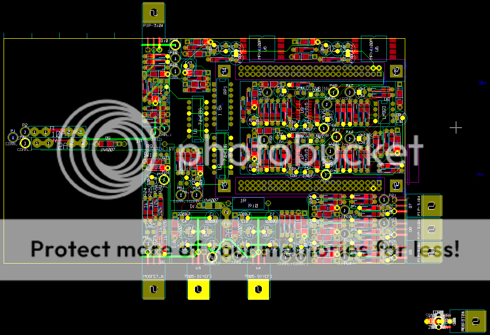
I'm going to have to find a better way to do the releases. I've been working on the theory that the schematic isn't changing so to note the PCB changed, I'm using the P.01, P.02, ect. However it doesn't let me reattach the PDF so for now, I guess you want to get the PDF schematics from the first A.XX release, then the latest KICAD files are in the P.0X releases.
This one is nearly good to go, I've got to look at the switched 5V supplies, route the traces (signals) to the TA card, and I've got to copy the injector and ignition drivers. That's about it. Right around the corner from asking folks to pick it apart. Then it will be time for the first fab, yeah.
https://sourceforge.net/project/showfil ... _id=624542
I've made significant progress on the PCB layout. Here's a snap shot.
I'm going to have to find a better way to do the releases. I've been working on the theory that the schematic isn't changing so to note the PCB changed, I'm using the P.01, P.02, ect. However it doesn't let me reattach the PDF so for now, I guess you want to get the PDF schematics from the first A.XX release, then the latest KICAD files are in the P.0X releases.
This one is nearly good to go, I've got to look at the switched 5V supplies, route the traces (signals) to the TA card, and I've got to copy the injector and ignition drivers. That's about it. Right around the corner from asking folks to pick it apart. Then it will be time for the first fab, yeah.

Re: freeEMS_1.0 rev A KICAD
A couple of comments just from your picture shown here. What is the board intended to fit in? If it is intended to fit in case where you slide the board in (like this) then you will need to leave out some space on the sides of the board for the slots (such as 3-4mm on each side with the example box in my link). If it will just be installed in whatever case is convenient such as a reused OEM box then you should plan to have a few mounting holes so that it can be mounted on standoffs. You'll then need the holes plus a big enough free space around them for the standoff.
Jean
Jean

Re: freeEMS_1.0 rev A KICAD
Mr Harvey,
Feel free to create a second release line called freeems.JH.PCB or something and release the pcb designs separately, perhaps indicating which schem revision they are based on in the versioning scheme you choose to use. The schematic release should be just that I reckon, thoughts?
Fred.
Feel free to create a second release line called freeems.JH.PCB or something and release the pcb designs separately, perhaps indicating which schem revision they are based on in the versioning scheme you choose to use. The schematic release should be just that I reckon, thoughts?
Fred.
DIYEFI.org - where Open Source means Open Source, and Free means Freedom
FreeEMS.org - the open source engine management system
FreeEMS dev diary and its comments thread and my turbo truck!
n00bs, do NOT PM or email tech questions! Use the forum!
The ever growing list of FreeEMS success stories!
FreeEMS.org - the open source engine management system
FreeEMS dev diary and its comments thread and my turbo truck!
n00bs, do NOT PM or email tech questions! Use the forum!
The ever growing list of FreeEMS success stories!
Re: freeEMS_1.0 rev A KICAD
I guess what I'll do is to release it as a separate file like you noted, I'll have to do it for a P.01 release as well, to keep the most recent SF release as the most up to date release. However, the PCB file from the P.01 release will be a duplicate of the files in the schematic A.XX release.
Hmmm, feels like there is a better way, but I guess that's the best there is.
Hmmm, feels like there is a better way, but I guess that's the best there is.
Re: freeEMS_1.0 rev A KICAD
It should be straight forward to strip the pcb stuff out of the zip file of the schem. Maybe it's too much hassle to do it that way, but maybe it's not. It's entire up to you man.
Fred.
Fred.
DIYEFI.org - where Open Source means Open Source, and Free means Freedom
FreeEMS.org - the open source engine management system
FreeEMS dev diary and its comments thread and my turbo truck!
n00bs, do NOT PM or email tech questions! Use the forum!
The ever growing list of FreeEMS success stories!
FreeEMS.org - the open source engine management system
FreeEMS dev diary and its comments thread and my turbo truck!
n00bs, do NOT PM or email tech questions! Use the forum!
The ever growing list of FreeEMS success stories!