I haven't worked on the Pi goodies for a little while now due to other factors. Ultimately, I still need to resolve hardware concerns before wrapping up software and the GPS logging falls somewhere in the middle as USB devices will need to be hard referenced during boot for consistent device mapping. Without that, software can't even recognize the correct devices as race conditions occur during boot and items are assigned different device IDs each time. Arbitrarily throw in a flash drive or somesuch and that would further complicate matters. I'm resolved to the fact that winter or not, I just need to get the hardware, in full, bolted in and working before correcting software from within an idling truck.
This means:
- Fix electrical. I'm not keen to run 12V constant through the firewall and into the dash, but it is what it is.
- Complete the IR screen surround and trust that 20mA won't overload the 3.3V GPIO pin that's already lending voltage to the PiCAD2 and RTC. More later on this.
- Run raw wires from the PiCAN2 CAN breakout to a DB9 male connector. Sadly, I bought female by mistake.
- Remove the HDMI cabling and install an ethernet cable. Change of plans for the gauge cluster.
Once all of that is done, the entire thing can be sealed and only software is left to resolve. This will mostly wrap up stage 1 (ECU) and 2 (HMI) and start sage 3 (gauge cluster).
I received a Pi Zero for Christmas and promptly spent more money on accessories. Though the intention was to use the Zero for staging software updates and changes to the Pi3 HMI unit, my long-term goal of creating an LCD gauge cluster has changed. It was initially going to be an HDMI screen off the Pi3 as part of a dual-head configuration. This sort of arrangement poses a number of problems that all go away if, instead, the LCD is driven by a Pi Zero that's preloaded with NodeJS and reads FreeEMS serial comms via TCP/IP from the HMI unit. Likewise, internet data can be IP forwarded from the HMI unit and all gauge display necessities remain on the actual gauge unit (the Pi Zero) instead of through a delicate dual-headed arrangement on an increasingly bogged down Pi3. The Pi Zero also presents a full array of GPIO pins for handing stepped-down indicator lamps.
After looking through wiring schematic, here's what will need to be interfaced (and can be pin-sensed at 3.3V and displayed via software):
Meters:
- Tach: From FreeEMS comms
- Speed: From VSS or accelerometer
- Fuel: From sender
- Water Temp: From FreeEMS comms
Rather than rely on associated alert lamps for the above meters, software alerts and actions can be created based on low-voltage levels for the absent meters. Meter voltage ranges are usually provided in repair manuals.
Lamps:
- Oil, low
- ABS
- MIL/CEL
- Washer fluid
- Seat belt
- Turn L
- Turn R
- High beam (headlights)
- Brake, low/parking brake
- SRS
- Overdrive, off
- Charge system
There might be a fuel open sockets for other sensors (transmission temp, 4WD engage, etc.) which aren't available on my truck, but have pre-existing wiring elsewhere. That might come in handy for custom sensor wiring later on.
Here are a few examples of cheap options to change 12-15VDC to 3.3V:
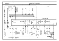
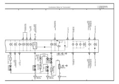
Wiring diagram for the the 2000-2004 Tacoma gauge cluster:
To power the Pi Zero, it would be nice to simply hang it off the existing Mausberry system I have for safe shutdown. For the display, that would be switched and requires 12VDC, approx 2.5-3A.