"89 Nissan Patrol Y60
-
masterkorp

- LQFP112 - Up with the play
- Posts: 171
- Joined: Tue Jan 17, 2012 11:21 am
- Location: Ponte de Lima, Portugal
-
masterkorp
- LQFP112 - Up with the play
- Posts: 171
- Joined: Tue Jan 17, 2012 11:21 am
- Location: Ponte de Lima, Portugal
Re: "89 Nissan Patrol Y60
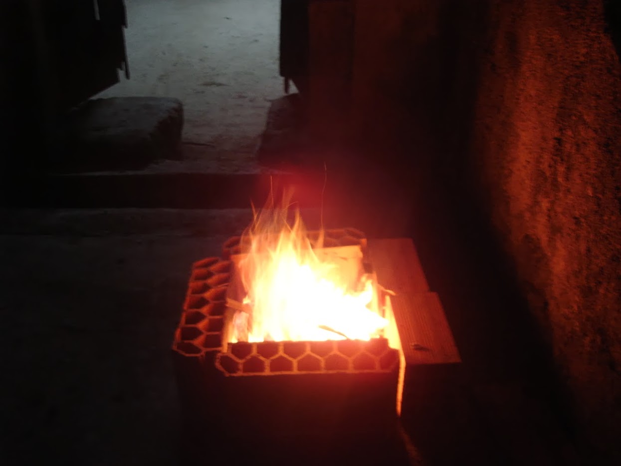
My super luxuous heating system, the nights are cold now.
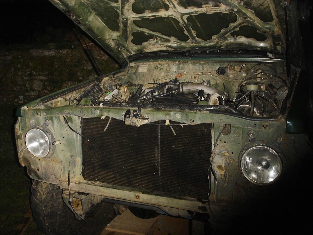
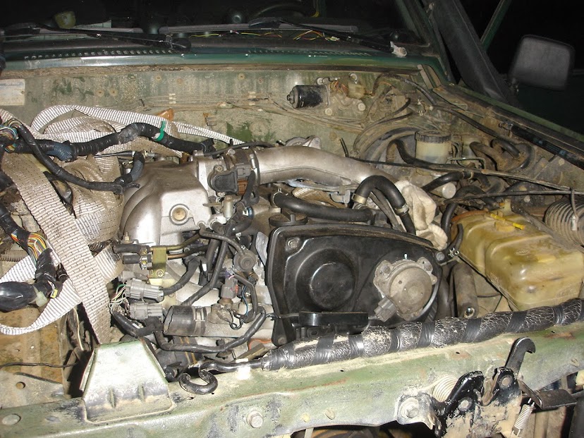
Its starts to look like a car again.
-
masterkorp
- LQFP112 - Up with the play
- Posts: 171
- Joined: Tue Jan 17, 2012 11:21 am
- Location: Ponte de Lima, Portugal
Re: "89 Nissan Patrol Y60
Okay i started soldering the jaguar 0.4 agains the OEM connector. I have 2 questions:
1) When I ordered the jaguar from Deuce, I didn't knew what rpm imputer combo to use, I asked him to to give me both Hall and VR resistor sets, because I have no idea what to use with Cam Angle Sensor, which ones should I use ? If I need to use anything else?
2) How should I wire up the ignition give I have 6 coils and the jaguar has 3 outputs ?

Re: "89 Nissan Patrol Y60
1 - For an Rb25 you will need a Hall setup. The OEM uses a logic IC and some protection/filter circuits made up out of passive components. I am not exactly sure what is available on the jag 0.4 you have to cater for this?
2 - Wasted spark FTW!
2 - Wasted spark FTW!

Re: "89 Nissan Patrol Y60
1 The RPM inputs on the 0.4 can be configured to be "good enough" for hall/nissan.
options:
2a from each ignition IC output, have two current limit resistors (you currently have just one) and run one from each channel to a different coil's ignitor channel
2b add another DIP8 IC to the board, run each IC output through a current limit resistor to an ignitor channel, and pair the inputs to the ICs at the CPU side to three pins
DIYEFI.org - where Open Source means Open Source, and Free means Freedom
FreeEMS.org - the open source engine management system
FreeEMS dev diary and its comments thread and my turbo truck!
n00bs, do NOT PM or email tech questions! Use the forum!
The ever growing list of FreeEMS success stories!
FreeEMS.org - the open source engine management system
FreeEMS dev diary and its comments thread and my turbo truck!
n00bs, do NOT PM or email tech questions! Use the forum!
The ever growing list of FreeEMS success stories!
-
masterkorp
- LQFP112 - Up with the play
- Posts: 171
- Joined: Tue Jan 17, 2012 11:21 am
- Location: Ponte de Lima, Portugal
Re: "89 Nissan Patrol Y60

Guys before doing any real silly stuff. I do think that the hall components are correct. Sorry for the quality my camera really sucks taking up close pictures.
-
DeuceEFI

- LQFP144 - On Top Of The Game
- Posts: 578
- Joined: Thu Feb 25, 2010 3:57 am
- Location: Gosport, IN USA
- Contact:
Re: "89 Nissan Patrol Y60
1) The resistor placement does look correct for Hall Effect inputs. The resistors should be 1k Ohm for the RPM0 and RPM1 inputs. You will also need to ground the RPM0- and RPM1- inputs for use with Hall Effect inputs.
2) For the ignition outputs you have Ignitor1, Ignitor2 and Ignitor3 outputs. The inputs to these circuits are IG1 (already connected via a trace to Port T2), IG2 (already connected via a trace to Port T3) and IG3 (which you will need to connect via a jumper wire to Port T4 (the square pad of P20 Port T4-7)).
2) For the ignition outputs you have Ignitor1, Ignitor2 and Ignitor3 outputs. The inputs to these circuits are IG1 (already connected via a trace to Port T2), IG2 (already connected via a trace to Port T3) and IG3 (which you will need to connect via a jumper wire to Port T4 (the square pad of P20 Port T4-7)).
Andy.
FreeEMS vehicle #11, 1932 Ford 5 Window Coupe with a 1996 GM 3.1L SFI V6 with DIS ignition
FreeEMS vehicle #16, 1996 Chevrolet S10 2.2L SFI I4 with DIS ignition
Owner of http://www.coolefi.com
FreeEMS vehicle #11, 1932 Ford 5 Window Coupe with a 1996 GM 3.1L SFI V6 with DIS ignition
FreeEMS vehicle #16, 1996 Chevrolet S10 2.2L SFI I4 with DIS ignition
Owner of http://www.coolefi.com