
I draw my wiring work on KiCAD
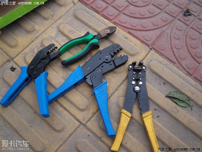
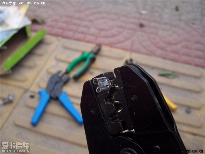
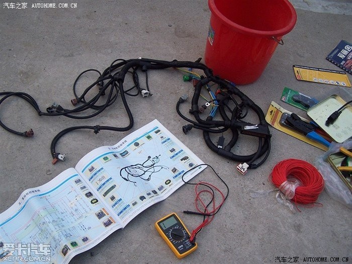
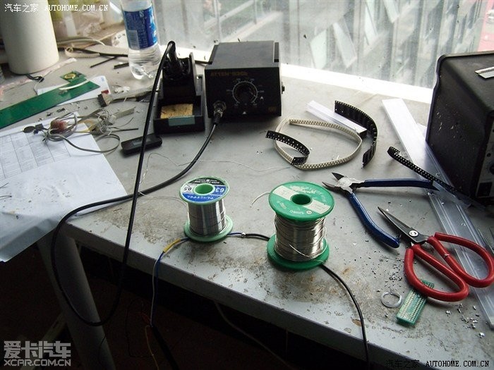
Crimping tool
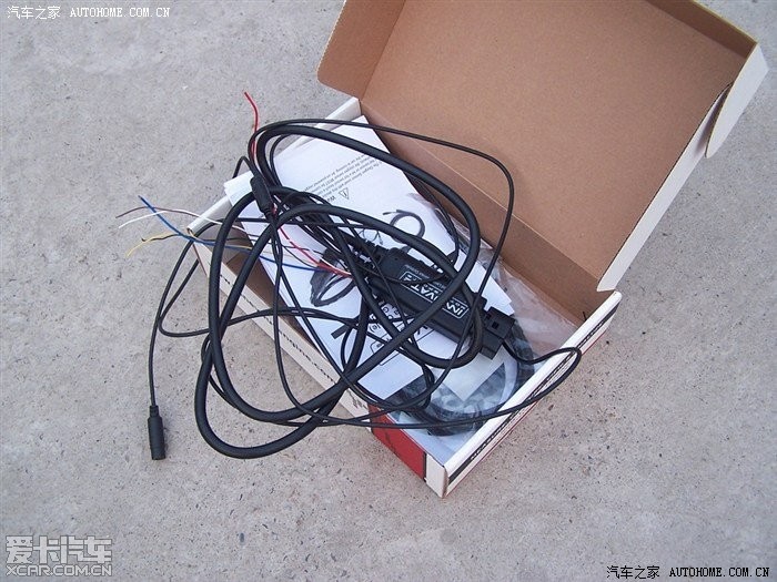
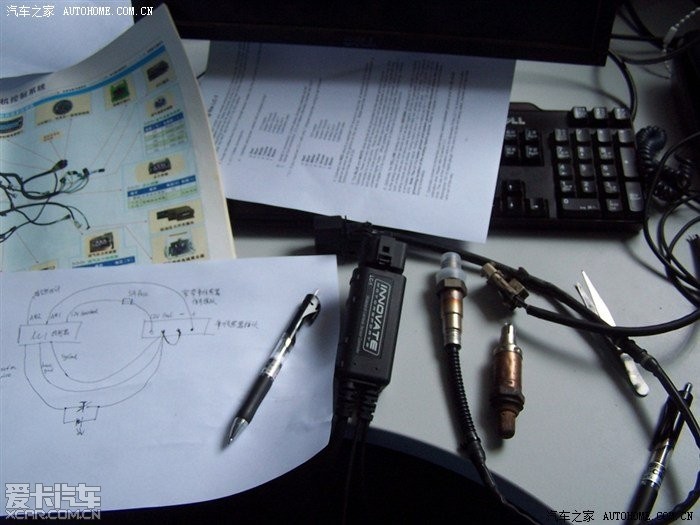
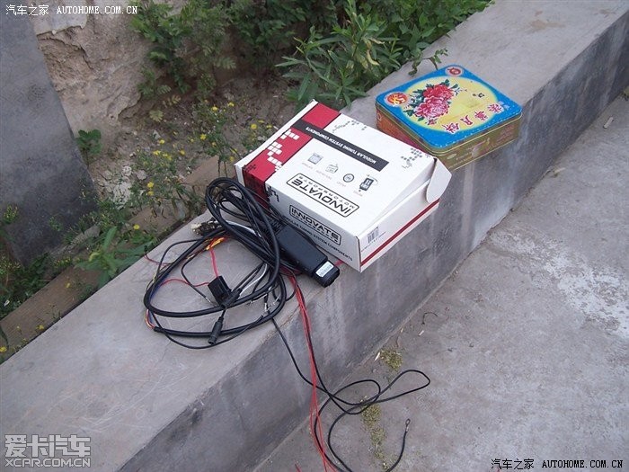
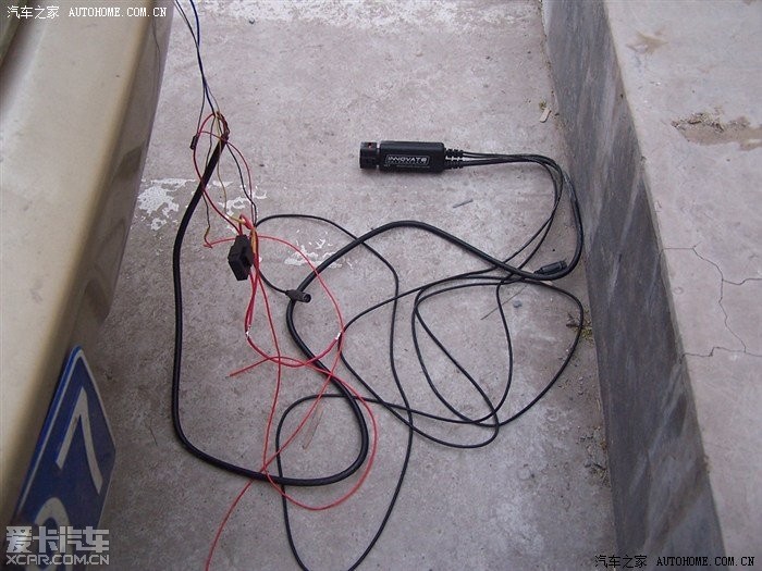
LC1
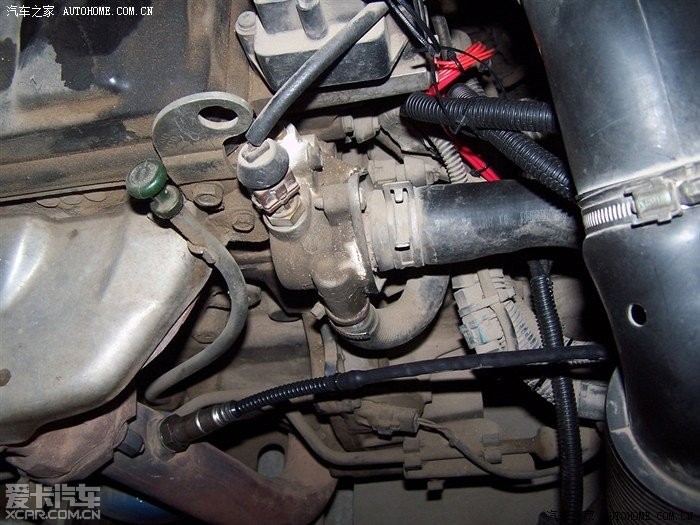
OEM O2 VS LSU4 O2
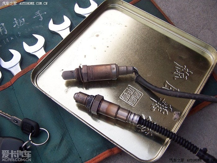
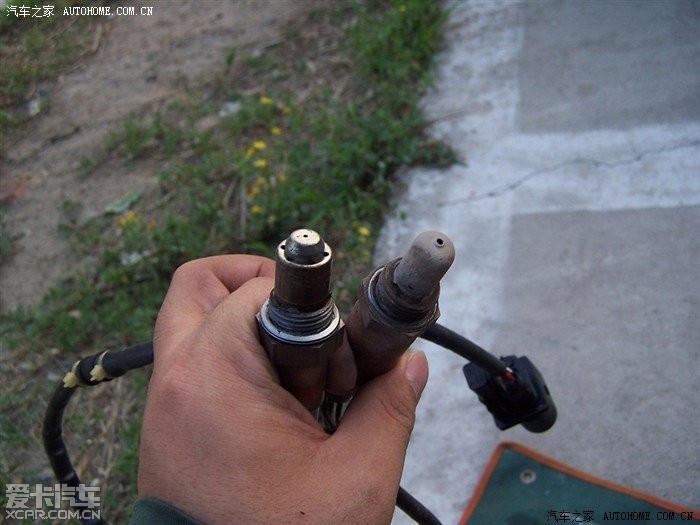
LSU4 O2 is geometry compatible with OEM O2
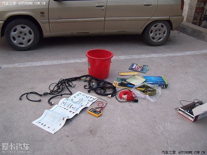
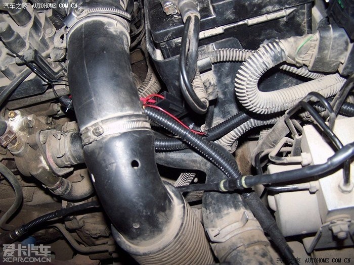
Study the OEM harness carefully
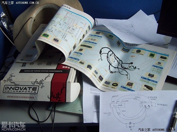
Draw my layout on paper to clear my idea
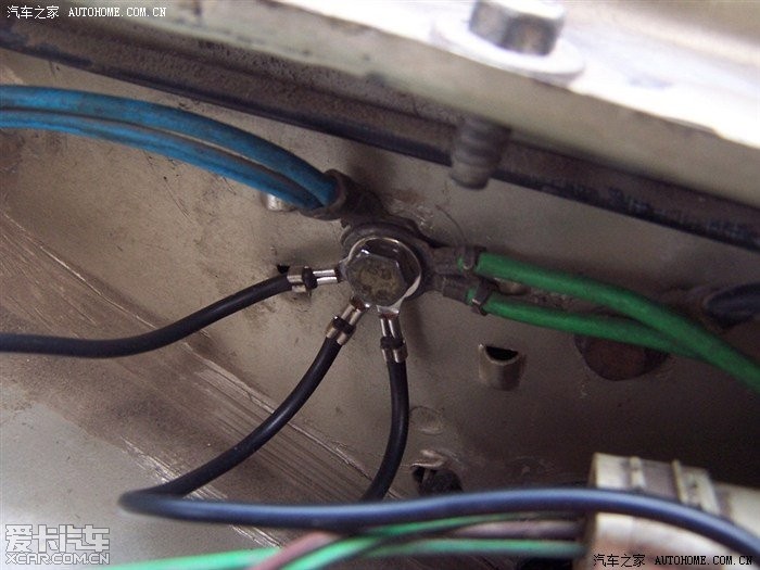
This layout is bad, I can't let LC1's ground and O2 signal ground converged too earlier at this point
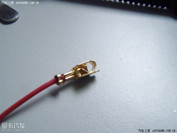
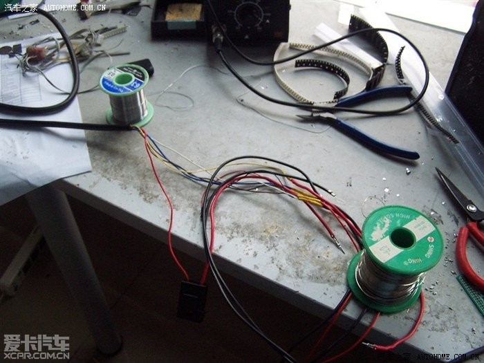
Crimp a node for fuse soecket
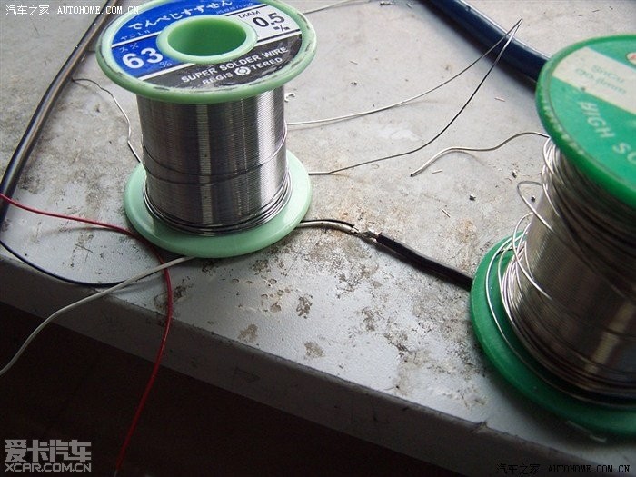
When possible, soldering is always better than crimping
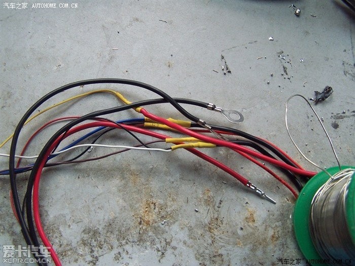
Use heat shrink tube to protect soldering point
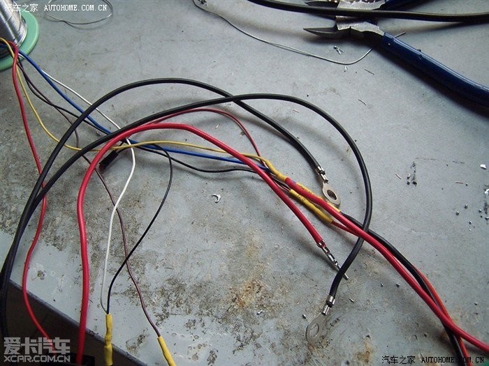
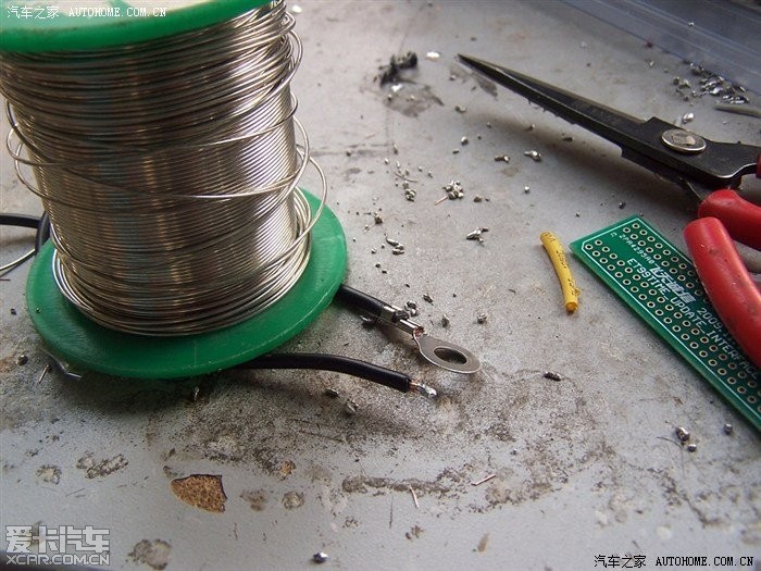
The wire from OEM O2 interface was not made of copper, so choose crimping
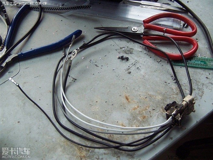
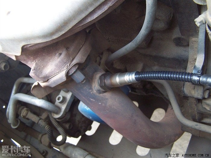
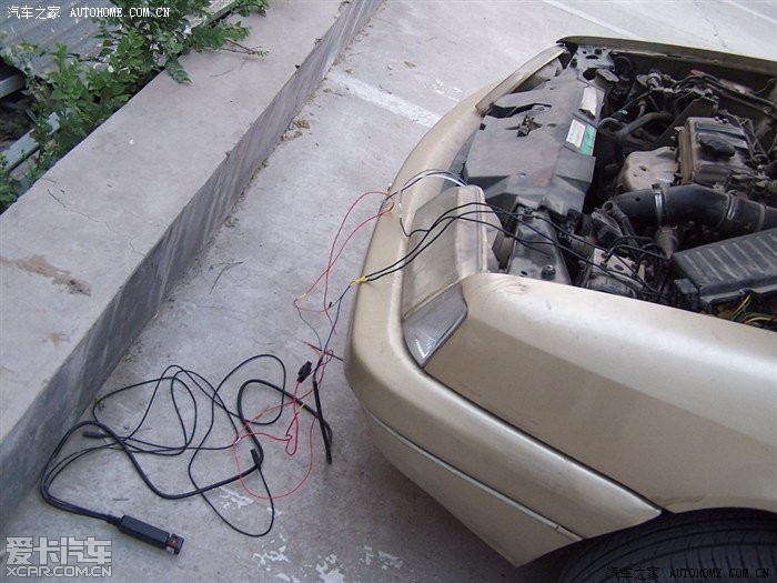
Ready to install
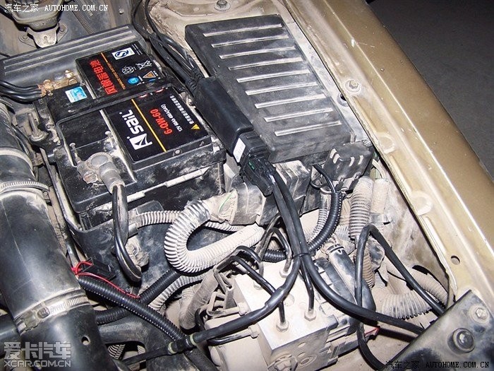
They must be ground at the same point as ECU were
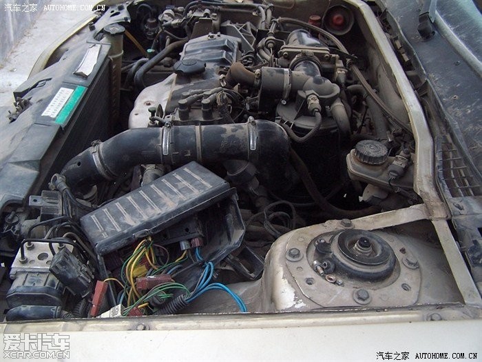
Have to uninstall relay and fuse box
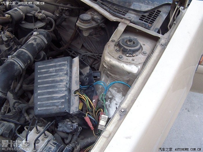
This is the ground I need
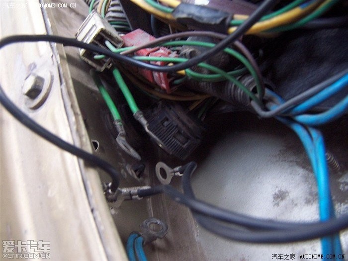
Multiple lugs on the same bolt is not optimal, but I have got no suittable lugs to crimp the three gnd wire together
move it
No problem, it's time to calibrate the LC1 and LSU4 O2 sensor
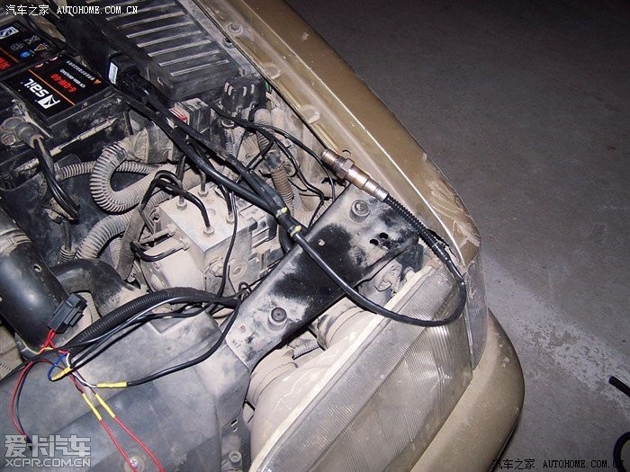
After all is done, push wire into corrugated tube
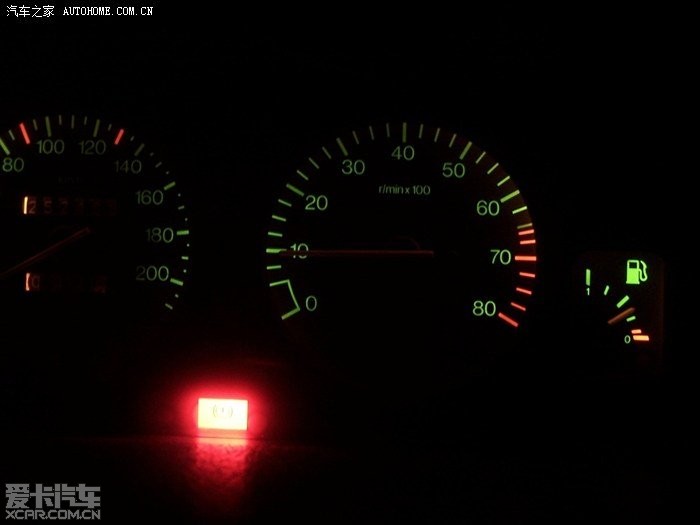
Idle is smooth and stable, check engine lamp won't light. The LC1 controller is smart enough to heat the sensor. I evaluate the resistance of OEM heater, It is only 5 omg, that's said the alternator must provide 2A+ current during the driving. And insufficient current can cause injectors squirt less than ECU expected, and a knock will be a result. The most significant effect was improving power/torque curve, the power output was more smooth than before and there's no free gaps on gas pedal
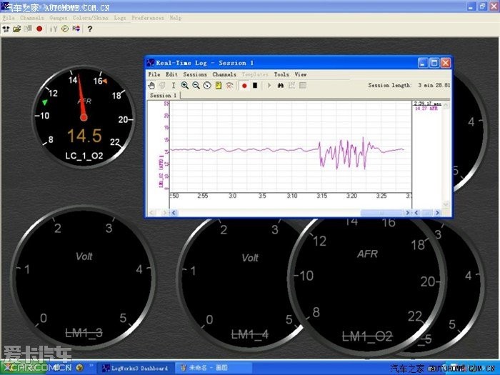
AFR at idle, I think it is a little rich. Using a notebook in order to monitor the AFR is awkward. So I decide to buy a bluetooth adapter to replace the RS232 cable and use my android pad to watch the AFR in real time

