OK. Ive been chattin with fred heaps on IRC.. Id LOVE !! to change from the megasquirt2v3 i currently have on my bike to fems (FreeEMS).
Now, id obviously need to do a fair bit of bench testing, and this is where the problem lies.
Id like to (help) develop a universal "simulator" board of sorts to help others develop firmware, code, etc..
My personal opinion of what it could / should contain:
12v input signal
12v output w/ 5v stepdown output
8 GREEN LEDs
8 RED LEDs
8 10k Trimpots, or possibly 250k pots, whatever.
Possibly some DIP switches to limit the use of some of the features. IE: you can "turn off" one of the trimpots so its a dud. Basically so you dont get too confused with too many inputs.
HALL + Optical input. This could be on a wire lead and mounted to a power drill with a tach wheel with some teeth or somethin. Thats totally up to the end user.. I personally have a 36-1 on my bike.. etc.
What else would be of benefit ? A COM data port ? USB with 256k flash could possibly simulate engine RPM tach signal, and a trimpot could "speed up" or "slow down" the pulsing to remove the hall / optical option ?
What would people want ?
If its not too complex, im happy to (help) design a layout, and provide eagle files to print your own, or possibly a kit for others at cost price. BUT this is all dependent on what we all come up with.
Think of it as a giant "jimstim" or somethin..
Simulator design, requirements wanted

Re: Simulator design, requirements wanted
I've seen talk about using a multi port sound card to do most of this. It would allow off the shelf hardware, and would be very flexible. Most signals are low bandwidth, and a sound card typically allows enough bandwidth for such experiments. Perhaps finding an external USB sound card would simplify the hardware side of it. I know of this chip that has linux support and is low cost.
http://images.qrvc.com/usbfob.pdf
I've used that device on a radio project I did a while back. That chip also includes a couple IO pins that can be used for misc options.
I guess I should ask what your strengths are. Hardware? Embedded software? PC software? Other?
As for features, I'd say to draft it for a couple engines, typically 2 hall/VR pickups, 2knock inputs, several ign/inj outputs, ext.
Re: Simulator design, requirements wanted
Thats quite an interesting approach. Me and fred were talkin in IRC and its possible to use some sort of AVR solution. Possibly arduino or a teensy++. The biggest delay would be writing firmware for it to do what is needed. Yes it could simulate your rpm and missing teeth perfectly, and have a trimpot adjust its pulse speed. Its also easily acceptable to have it accept a hall sensor or optical sensor and use a power drill with your preferred tach teeth setup on it. Ive already done this on a teensy++ and optical sensor. It outputs data on a serial channel in plain text, but can output it basically any way you want. On a digital pin in pulses or whatever.
Has plenty of inputs / outputs too.. So could power a bunch of LEDs to show actual outputs from hardware, and inputs to simulate other things on ADC. Use trimpots to do it..
This way would detract from what its actually ment to achieve. Yes it would work, BUT firmware has to be done, and has to be tested, etc.. Yet another delay from the main project. If a simple circuit is designed, then anyone could make it on a breadboard, and no programming is required.. "build it and go" so more dev time is spent on the actual project.
Each method has its pro's and con's.
As for my area of expertise. Thats sort of an interesting point. Its hard to describe. I can hack software to some extent, but im not a programmer. I can build hardware and circuits, but im not an engineer. I just tend to hack WAY too much. I also pick things up surprisingly quick. I guess its "give me an objective, ill achieve it".
I provide bulk grunt work on many projects. My real expertise is .. err. im a tradesman. I built a digital flowbench, im almost finished a dyno, which i built from scratch, etc.. I do what is required to do, to get a project done well.. If any of this makes sense.
I have access to some fairly smart dudes, software and hardware. Plus a bunch of other things. So i do what i can, and get the rest done with beers I just tend to be fairly resourceful. Does any of this make sense ?
Incidently, my dyno is 4 teeth sensor wheel, optical sensor, hooked to a teensy++
Has plenty of inputs / outputs too.. So could power a bunch of LEDs to show actual outputs from hardware, and inputs to simulate other things on ADC. Use trimpots to do it..
This way would detract from what its actually ment to achieve. Yes it would work, BUT firmware has to be done, and has to be tested, etc.. Yet another delay from the main project. If a simple circuit is designed, then anyone could make it on a breadboard, and no programming is required.. "build it and go" so more dev time is spent on the actual project.
Each method has its pro's and con's.
As for my area of expertise. Thats sort of an interesting point. Its hard to describe. I can hack software to some extent, but im not a programmer. I can build hardware and circuits, but im not an engineer. I just tend to hack WAY too much. I also pick things up surprisingly quick. I guess its "give me an objective, ill achieve it".
I provide bulk grunt work on many projects. My real expertise is .. err. im a tradesman. I built a digital flowbench, im almost finished a dyno, which i built from scratch, etc.. I do what is required to do, to get a project done well.. If any of this makes sense.
I have access to some fairly smart dudes, software and hardware. Plus a bunch of other things. So i do what i can, and get the rest done with beers
Incidently, my dyno is 4 teeth sensor wheel, optical sensor, hooked to a teensy++
Re: Simulator design, requirements wanted
I guess a first question to resolve is, what's the purpose of such a test device. It can be handy for checking your solder skills on a newly made DIY board, and it can be handy for developing against with out a motor or extra hardware present.
If you went with with a PC based approach, I would probably recommend using the signal processing capabilities of GNURadio, with some sound cards. The only part that would be custom is a wire harness. I like this approach, because it doesn't require a scope, you can simulate the scope with software. To make that approach work you would need to piece virtual blocks together with python scripts, such that they can display things on a screen. GNURadio consists of signal processing blocks made from compiled C files. These blocks get connected together and used via python scripts. It might be worth a look.
If you go with the hardware based system, I wouldn't recommend an AVR system. They are expensive and limiting in capabilities. AVR's are good for low power draw, and devices like those you mentioned above, make programming and prototyping a bit easier. However, they will require a custom shield or interface board. So why not just make it all custom? If you go all custom, I would recommend an ARM based processor partly for cost constraints, but mostly for flexibility. ARM processors can be found with just about any set of interfaces around them you could dream of. ARM's also have easy to use tools like mbed. I believe mbed is doing a contest right now, you might be able to sign up and get free hardware. I recall seeing something in circuit cellar about that.
It sounds like you may already have a base AVR hardware based system to work from. If so great, I'll look forward to learning about it. If it's early enough that I can steer you to what might be a better solution, I'll make some recommendations, as I did above. I'm not familiar with teensy++, I'll add that to my list to learn about.
Once you make a decision on what general direction you want to go, I'll see if I can chime in and help out as it goes along.
-
nitrousnrg

- LQFP144 - On Top Of The Game
- Posts: 468
- Joined: Tue Jun 24, 2008 5:31 pm
Re: Simulator design, requirements wanted
I can share my experience here..
A few years ago I developed my own ecu, and I used some tools for testing. Firmware simulation was useless, mostly because I couldn't simulate noise, and simulate the crank signals was so f*** hard I couldn't do it.
So, I put hands on attaching a (quite big) AC motor to a crank wheel, 60-2 teeth. The thing is, having a moving part isn't handy at all. My debugs were short, noisy and a little dangerous. I ended hurrying up the engine setup to move the testing to the car. I remember my first approach was a little motor with an optical sensor to provide a crank signal. That sucks: horribly inaccurate, moving parts, and I needed to test my hand made LM1815 replacement, so 0-5v signals were useless.
If I had to make it now, I'd use simple components, just to provide a few leds and digital/analog inputs (pots and switches), and I'd generate the crank and cam signals with the PC audio card. I believe it is possible to generate those signals, I should check if the output frequencies are acceptable (there is no DC, for example).
My reasons for that are that it could be powered directly from my laptop (USB power + audio jack), so I can use it in the testbench or in the car.
I have an mbed board here, and I find it really useful (except for the compiler license). It has ADC, DAC etc, but depending on a commercial platform isn't good if the intention is to allow people to do it themselves. Besides of that, I can recommend an mbed or other arm microcontroller. Never tried avr though (I wrote some firmware, but never deployed it).
So, if I had to make it, I'd choose a simpler pc solution. Right now I don't have the time to write firmware code to generate different crank signals.
I hope this helps
Marcos

Re: Simulator design, requirements wanted
I really need to get onto this! I prompted Quan to post this thread, and I have a clear idea of what I want, but I need to spec it and articulate that here.
DIYEFI.org - where Open Source means Open Source, and Free means Freedom
FreeEMS.org - the open source engine management system
FreeEMS dev diary and its comments thread and my turbo truck!
n00bs, do NOT PM or email tech questions! Use the forum!
The ever growing list of FreeEMS success stories!
FreeEMS.org - the open source engine management system
FreeEMS dev diary and its comments thread and my turbo truck!
n00bs, do NOT PM or email tech questions! Use the forum!
The ever growing list of FreeEMS success stories!
-
nitrousnrg
- LQFP144 - On Top Of The Game
- Posts: 468
- Joined: Tue Jun 24, 2008 5:31 pm
Re: Simulator design, requirements wanted
Now I remeber I have a video of it.
http://www.youtube.com/watch?v=yOOCg2-- ... 3iQqT2b4tE
At 00:00 you can see the crank wheel+motor, at 00:16 the switches and a 0-5v square wave generator to emulate the 60-2 teeth wheel (I used a microcontroller for that).
Awful setup.
http://www.youtube.com/watch?v=yOOCg2-- ... 3iQqT2b4tE
At 00:00 you can see the crank wheel+motor, at 00:16 the switches and a 0-5v square wave generator to emulate the 60-2 teeth wheel (I used a microcontroller for that).
Awful setup.
Marcos
Re: Simulator design, requirements wanted
mmm wine! Yes, your test rig is a mess alright :-)
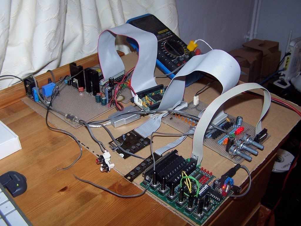
For reference, what I'm looking to do is replace this :
http://i260.photobucket.com/albums/ii15 ... 0_8206.jpg
I definitely need to write up the purpose... but it just went down the list a little. Don't panic, though, I'll get there!
Fred.
For reference, what I'm looking to do is replace this :
http://i260.photobucket.com/albums/ii15 ... 0_8206.jpg
I definitely need to write up the purpose... but it just went down the list a little. Don't panic, though, I'll get there!
Fred.
DIYEFI.org - where Open Source means Open Source, and Free means Freedom
FreeEMS.org - the open source engine management system
FreeEMS dev diary and its comments thread and my turbo truck!
n00bs, do NOT PM or email tech questions! Use the forum!
The ever growing list of FreeEMS success stories!
FreeEMS.org - the open source engine management system
FreeEMS dev diary and its comments thread and my turbo truck!
n00bs, do NOT PM or email tech questions! Use the forum!
The ever growing list of FreeEMS success stories!