FreeEMS hardware feature wishlist (your suggestions here!)

From DIY contraptions to sophisticated FreeEMS-specific designs! Plus general hardware development!
Post Reply
User avatar
Fred
Moderator
Posts: 15431
Joined: Tue Jan 15, 2008 2:31 pm
Location: Home sweet home!
Contact:

FreeEMS hardware feature wishlist (your suggestions here!)

Post by Fred »

I'll keep this post as up to date as I can. Feel free to suggest categories for them as well.

There are some preliminary designs in the works, I will post them here as soon as I can.

Feel free to share your thoughts on what should and shouldn't be on the board(s).

The most important ones are those that can be applied to any engine.

Anywhere from general ideas to fine details are ok.

Thank you in advance for your input.

The list (for the initial version) :
  • General
    • Sandwich construction
    • FM Adapt board on top for upgradeable processor options
    • Input board in the middle, 160mm x 100mm Eurocard form factor
    • Output board below that, 160mm x 100mm Eurocard form factor
    • Further boards can be added above and below the 3 base boards
    • All 100 pins passed through every board
    • Where space allows, prototyping areas on the main two boards, but this is not required as extra boards can be added to the sandwich with ease
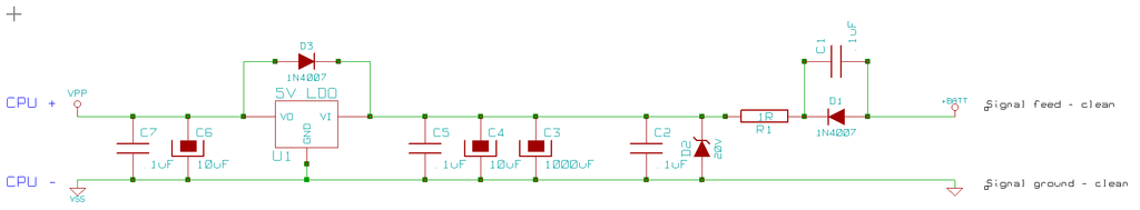
  • Power
    • Separate battery feeds for MCU supply/sensor supply, High power devices, Battery reference (4)
    • Separate grounds for signal/MCU/sensor/reference and High power devices (3)
    • MCU supply VERY well filtered and protected
    • Zener clamp/regulator at around 20V for MCU
    • Reverse voltage protection diode and possibly fuse
    • Series Diode for revers protection too (possibly not as the voltage loss may be intolerable)
    • Fused heavy power and ground lines (large values for reliability)
    • Reverse voltage and clamping/clean up on the heavy power and ground feeds too.
    • Independent filter return pins for these
    • High power series resistor that can stomach 15V continuously for the previous two features.
    • Good sized reservoir capacitor to supply the MCU during low transients
    • Sensor 5v reference voltage using own self protected regulator
    • MCU LDO regulator on processor board
  • Input board features
    • 1 or 2 layer only (easily printable at home)
    • At least 50 built in input conditioning circuits total
    • Sensitive inputs at same end of the board as the MCU
    • Multiple VR sensor inputs provisioned (discrete or integrated) : 3x engine, 4x wheel, 1x drive shaft, ???
    • All 16 ADC channels provided with multi configurable setup (input impedance resistor, series resistor, internal filter cap, external filter cap, ??)
    • General digital IO filter circuits provided for most pins (same as or similar to ADC input circuits)
    • Space for up to 4 MAP sensors (pre-intercooler, post-intercooler/pre-throttle, manifold/ports, altitude OR 4cyl multiplexed ITB use (chosen in software)
    • All input pins clamped with 5V1 zeners
    • All input pins reverse voltage protected with signal to ground reverse biased diode
    • All input pins current limited with 1.6k resistors
    • All input pins filtered at the CPU with a capacitor of application dependent size
    • Pull up (5V) and/or downs (0V) provisioned for all MCU pins that do not have built in ones
  • Output board features
    • 1 or 2 layer only (easily printable at home)
    • At least 50 built in output drive circuits total
    • High current stuff positioned at the far end of the board from the MCU (and on the bottom side)
    • Provision for 24 heat-sinked high current devices in to220 and/or DPAK form for driving injectors, coils, relays, solenoids, fans, pumps etc
    • Provision for at least 50 to92 pre-driver transistors/FETs of a common pin out with triangle footprint (jumper out otherwise)
    • As many as possible configured for high side OR low side use via jumpers
    • Provision for optional P&H chips before the 6 injector drivers (jumper out otherwise)
    • Provision for pull up or pull down for each pin by way of four pads in square layout for vertical resistor (0,5,12,Out)
    • Provision for remote current sense resistor on at least the 6 injector outputs (jumper out otherwise)
    • All output pins current limited with 1.6k resistors
  • Add on compatibility features
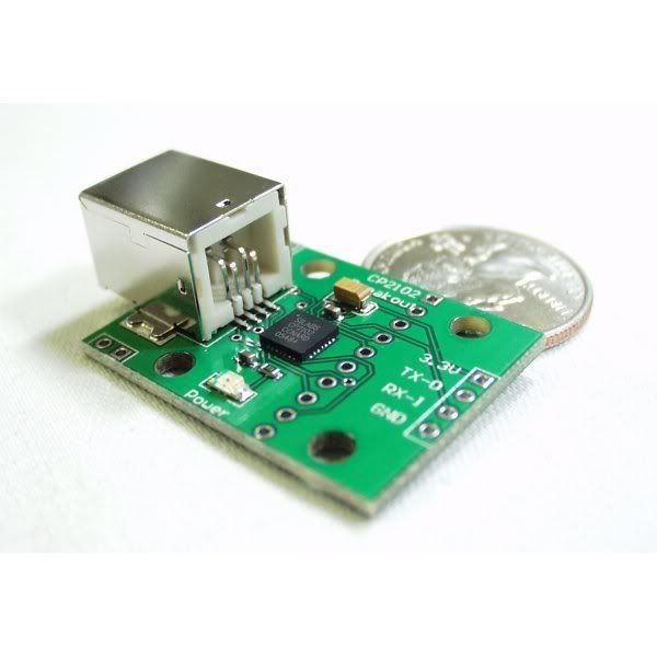
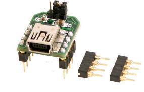
    • Headers provided for SCI/SPI/IIC/CAN etc for easy interface to boards as shown below
    • ???
Fred.
DIYEFI.org - where Open Source means Open Source, and Free means Freedom
FreeEMS.org - the open source engine management system
FreeEMS dev diary and its comments thread and my turbo truck!
n00bs, do NOT PM or email tech questions! Use the forum!
The ever growing list of FreeEMS success stories!
User avatar
ababkin
LQFP112 - Up with the play
Posts: 215
Joined: Tue Jan 15, 2008 5:14 pm

Re: freeEMS hardware feature wishlist (your suggestions here!)

Post by ababkin »

Here is something i'd like to see. This probably isn't a new idea but still...

1. As we know, the MCU likes clean power. However cars happen to have very dirty power (we're talking about electrical power here, you power freaks :twisted: ).

2. To account for fluctuations in the "dirty" power, the EMS (ECU) has a circuit that references the power source and also has special maps, which let the EMS know how to change the way it controls the engine depending on the power level at any instant (e.g. injector "open time" and coil dwell are the two examples that are usually implemented as a function of reference voltage in the power line, among their other arguments).

3. Some employ "power cleaning" circuits to clean up the power thats going to the EMS. But one should keep in mind the fact that the power driving coils and injectors in a car is still dirty even if the EMS's power has been cleaned up.
If the power level is referenced by ECU at it's own "power inlet", it will only see the clean power that it's being fed and therefore won't have the correct reading about the power level that for example injectors and coils are seeing.

This discrepancy may affect tuning negatively, just like incorrectly setup values in the injector open-time and/or dwell voltage correction tables.

Proposed solution:
To not put the the "power source" and "voltage reference" on the same line. Rather have the reference line feeding from the dirty power lines and have the ECU's power cleaned up with power conditioning circuits. (buffered with bypass caps, etc..)
Legal disclaimer for all my posts: I'm not responsible for anything, you are responsible for everything. This is an open and free world with no strings attached.
User avatar
Fred
Moderator
Posts: 15431
Joined: Tue Jan 15, 2008 2:31 pm
Location: Home sweet home!
Contact:

Re: freeEMS hardware feature wishlist (your suggestions here!)

Post by Fred »

Alex, you are 100% right, the supply and reference should be separated. The current design I have drawn up has three power feeds and two ground feeds for exactly this purpose and one other purpose also.

Preliminary pin listings :
Power ground
Signal ground
Signal supply
Power supply
Battery reference

Power supply and power ground will NOT be coupled to the signal supply and power. By keeping them totally isolated heavy loads can be driven from inside the EMS without affecting the supply of clean juice to the CPU at all. Because they will both be referenced in TRUE star grounding technique at the block or battery, the voltage differentials at the drive transistors/FETs bases/gates will be minimal and not affect operation at all. At the same time because the current drawn by those devices is not causing a loss of potential on the signal reference ground all sensor voltages will remain accurate provided that the installer has done the job right. Additionally the battery reference will be isolated too such that it is unhindered by the heavy filtration for supply to the CPU and unhindered by the large drops in potential caused by current flowing down the power supply line.

However, the battery reference feed still needs to be clean. To this end it WILL be filtered significantly. The reason this is OK is that primarily you are looking for a moving average of where the battery is sitting, you do NOT want to know about instantaneous fluctuations caused by coil, injector, etc turn on/off, only things like fans/windscreen heaters etc that come on and stay on. The filtration we are talking about is only useful over a very short time period anyway. IE the source impedance of the supply to the battery reference filter circuit is very low indeed and thus will drive the voltages there in a servo like manner.

The primary advantage of such a circuit layout is NOT having your sensor voltages toyed with by other signal fluctuations. In this way all inputs should be the most accurate representation of reality possible. Some other EMS's currently DO NOT hit the mark in this respect and cause numerous issues with installations that don't work around their design properly.

I hope that clarifies the situation somewhat.

Thank you,

Admin.
DIYEFI.org - where Open Source means Open Source, and Free means Freedom
FreeEMS.org - the open source engine management system
FreeEMS dev diary and its comments thread and my turbo truck!
n00bs, do NOT PM or email tech questions! Use the forum!
The ever growing list of FreeEMS success stories!
User avatar
Fred
Moderator
Posts: 15431
Joined: Tue Jan 15, 2008 2:31 pm
Location: Home sweet home!
Contact:

Re: freeEMS hardware feature wishlist (your suggestions here!)

Post by Fred »

Because of known issues with the quality of RS232 serial comms, alongside implementing some checksumming in the firmware and tuning software using this chip on board is going to keep the errors low and speed high.

Image

http://www.sparkfun.com/commerce/produc ... cts_id=198
http://www.sparkfun.com/commerce/produc ... cts_id=310
http://www.sparkfun.com/datasheets/IC/cp2102.pdf

There is no requirement to use the second on board max232 channel, and the pins that drive it come out on the 100pin footprint anyway, and thus can be routed to some pads on one of the main boards and either this chip or this little board mounted there to interface with it. The option for those who want to go cheap to use the onboard max chip is still there, or those looking for a better solution can go ahead and install one of these.

Admin.
DIYEFI.org - where Open Source means Open Source, and Free means Freedom
FreeEMS.org - the open source engine management system
FreeEMS dev diary and its comments thread and my turbo truck!
n00bs, do NOT PM or email tech questions! Use the forum!
The ever growing list of FreeEMS success stories!
User avatar
Fred
Moderator
Posts: 15431
Joined: Tue Jan 15, 2008 2:31 pm
Location: Home sweet home!
Contact:

Re: freeEMS hardware feature wishlist (your suggestions here!)

Post by Fred »

Hi, here are some ideas for prototyping area in the middle of our main boards :

softec 9s12xdp512 proto board proto area :
http://www.s12x.com/images/sks12xdp512a/P1010063a.jpg
full resolution
http://www.s12x.com/images/sks12xdp512a/P1010063.JPG

closeup of processor :
http://www.s12x.com/images/sks12xdp512a/P1010076a.jpg
full resolution
http://www.s12x.com/images/sks12xdp512a/P1010076.JPG

Note the locations for IC's and the power busses along each side with PLENTY of pins, not 2 of each...

Admin.
DIYEFI.org - where Open Source means Open Source, and Free means Freedom
FreeEMS.org - the open source engine management system
FreeEMS dev diary and its comments thread and my turbo truck!
n00bs, do NOT PM or email tech questions! Use the forum!
The ever growing list of FreeEMS success stories!
User avatar
Fred
Moderator
Posts: 15431
Joined: Tue Jan 15, 2008 2:31 pm
Location: Home sweet home!
Contact:

Re: freeEMS hardware feature wishlist (your suggestions here!)

Post by Fred »

Not everyone is going to want this (only track day enthusiasts really) but this would be easy to interface with and datalog :

Image

http://www.evbplus.com/tinybee_accelerometer_3axis.html

application notes :
http://www.kionix.com/sensors/application-notes.html

It would be nice to have it real time correlated with rpm, gear, afr, etc. It would also make tuning for best torque less guess work on non knock limited engines.

Admin.
DIYEFI.org - where Open Source means Open Source, and Free means Freedom
FreeEMS.org - the open source engine management system
FreeEMS dev diary and its comments thread and my turbo truck!
n00bs, do NOT PM or email tech questions! Use the forum!
The ever growing list of FreeEMS success stories!
User avatar
Fred
Moderator
Posts: 15431
Joined: Tue Jan 15, 2008 2:31 pm
Location: Home sweet home!
Contact:

Re: freeEMS hardware feature wishlist (your suggestions here!)

Post by Fred »

Another alternative for usb <> uart interface doing away with the rs232 physical transfer layer :

Image

http://www.ftdichip.com/Products/Evalua ... MM232R.htm
http://apple.clickandbuild.com/cnb/shop ... tle=MM232R

...and EVEN smaller :

Image

http://www.ftdichip.com/Products/Evalua ... UB232R.htm
http://apple.clickandbuild.com/cnb/shop ... tle=UB232R

On another note, this board has a usb host controller with transparent fat support on it! that means super easy datalogging to a usb hard drive (flash or full on big disk) :

Image

http://www.vinculum.com/prd_vnc1l.html
http://www.saelig.com/miva/merchant.mvc ... Code=UI1E3

It's cheap enough, and should be dead simple to write an interface for. It should also leave you with virtually unlimited datalogging for continuous runs on track, or long drives etc etc etc.

Pretty cool little device really.

Admin.
DIYEFI.org - where Open Source means Open Source, and Free means Freedom
FreeEMS.org - the open source engine management system
FreeEMS dev diary and its comments thread and my turbo truck!
n00bs, do NOT PM or email tech questions! Use the forum!
The ever growing list of FreeEMS success stories!
User avatar
Fred
Moderator
Posts: 15431
Joined: Tue Jan 15, 2008 2:31 pm
Location: Home sweet home!
Contact:

Re: freeEMS hardware feature wishlist (your suggestions here!)

Post by Fred »

For power MOSFETs I propose the use of TO220 parts for a number of reasons :
compatibility
durability
current handling capability
ease of fitment
ease of replacement
heat dissipation

and if used like this :

Image

Image

they will take up very little real estate.

I found a philips part thats compatible with other common FETS with full auto protection and 8 amp current handling for 2.68NZ each. I ordered 12 of them. They are direct from CPU drive, and can power High Z injectors (several per channel) and any relay or solenoid like PWM idle valves, stepper motors (with a driver chip), fuel pump cut off, fan switch on etc etc etc.

Additionally because they are so universal, for a mere $5NZ each, 20amp versions were available. You simply cant blow such devices, they have output voltage clamps, input ESD protection, overheat shutoff, over current shut off, etc etc. great devices.

I propose the use of TO92 packaged light weight versions for driving of external ignition modules with an on board pull up. the use of only these two devices for outputs will keep board design 5 year old simple and provide a robust and generic set of output pins for virtually any use.

Admin.
DIYEFI.org - where Open Source means Open Source, and Free means Freedom
FreeEMS.org - the open source engine management system
FreeEMS dev diary and its comments thread and my turbo truck!
n00bs, do NOT PM or email tech questions! Use the forum!
The ever growing list of FreeEMS success stories!
User avatar
Fred
Moderator
Posts: 15431
Joined: Tue Jan 15, 2008 2:31 pm
Location: Home sweet home!
Contact:

Re: freeEMS hardware feature wishlist (your suggestions here!)

Post by Fred »

Here's a software example for use with the FTDI serial part above (parallel mode i think?)

http://www.rasmicro.com/USB.htm

Admin.
DIYEFI.org - where Open Source means Open Source, and Free means Freedom
FreeEMS.org - the open source engine management system
FreeEMS dev diary and its comments thread and my turbo truck!
n00bs, do NOT PM or email tech questions! Use the forum!
The ever growing list of FreeEMS success stories!
User avatar
Fred
Moderator
Posts: 15431
Joined: Tue Jan 15, 2008 2:31 pm
Location: Home sweet home!
Contact:

Re: freeEMS hardware feature wishlist (your suggestions here!)

Post by Fred »

Further to Alex's comments above, and related to him linking me to Freescale AN2201, I've been thinking about CPU power supply input topology.

Firstly, I don't think its reasonable to expect the EMS to have to deal with operation below the 6v level it is capable of operating at.

However, I have some ideas to get around this and at the same time deal with the other issue of noise on the CPU feed line.

Image

Starting from right and moving to the left we have in order :
  • Power feed and ground from battery and/or block
  • Reverse polarity hook up protection diode
  • Snubbing capacitor for that diode (diodes are electrically noisy when they switch on and off)
  • Current limiting resistor (value yet to be calculated)
  • Zener over voltage clamping diode (voltage yet to be determined, but must be below the max voltage of the components following it)
  • Snubbing capacitor for that diode (diodes are electrically noisy when they switch on and off)
  • Charge storage electrolytic polarised 25V 1000uF capacitor (value may change, but 220 - 2200 is around what we want)
  • High frequency tantalum 25V 10uF capacitor (35V units are expensive, as are 22uF)
  • Ultra high frequency ceramic 0.1uF capacitor (larger units with similar frequency response would also be acceptable)
  • 5V LDO (low drop out) voltage regulator
  • Reverse voltage protection diode for the regulator in case of external capacitors discharging more quickly and/or to a lower level than internal ones (snubbing not required as this will not happen when things are actually running)
  • High frequency tantalum 25V 10uF capacitor (35V units are expensive, as are 22uF)
  • Ultra high frequency ceramic 0.1uF capacitor (larger units with similar frequency response would also be acceptable)
  • Power feed and ground for CPU core
The interesting points about this are :
  • Low voltage MOV's are nice, but are also expensive and hard to find in some places so are not used
  • Series resistor and Zener are cheap, readily available everywhere and will do the same job to some extent
  • The series resistor also forms part of a simple first order low pass filter with the capacitors inside it. This improves noise immunity even more and lightens the load on the Zener.
  • Reverse voltage protection diode is dual purpose, purpose 1 is to not allow things to get cooked when you hook it up backwards, purpose 2 is to prevent the caps discharging back into the battery during short term low voltage conditions such as starting.
  • The sizable electrolytic capacitor will store enough charge to supply the ecu for a significant period of time should there be a continued low voltage starting condition, or when you turn off the key, now, if you also put a relay in between the battery voltage reference line (not pictured) such that when the key is turned off, the power is cut to that feed too, the ecu can detect that its about to run out of juice and store its current state to an eeprom. this can aid in cold/hot starting ease. it would of course also need to use a time source in order for that to be useful, but i have such a chip on the way, and such features are at the bottom of the list anyway.
  • The board we are using comes with an LDO reg on board, but it can only supply 100mA, part of this diagram already exists on the board. the balance can go on our lower main board. a parallel circuit and regulator can be used to feed the TPS and any other external sensors that require 5v further isolating the cpu from external influences. if there is sufficient but not excessive voltage difference between the two 5v supplies, the external one can be used for the ADC voltage reference. I doubt this will be necessary however. another option is to ditch the onboard vreg and supply both from one on the main board. If this is done, the supply would need to be protected from external influences by something like a polyfuse as is commonly used in tweeter speaker applications.
Comments?

Admin.
DIYEFI.org - where Open Source means Open Source, and Free means Freedom
FreeEMS.org - the open source engine management system
FreeEMS dev diary and its comments thread and my turbo truck!
n00bs, do NOT PM or email tech questions! Use the forum!
The ever growing list of FreeEMS success stories!
Post Reply