
I have to admit I've been thinking of similar, but with AVR. AVR is a bit more open, and a bit more robust. What I was thinking of was for a way to get firmware to a sub processor. I would want one PC connection for the upload, and I wouldn't want to have to take the chip out of it's socket to send it a new firmware.
Probably the easiest way, is to upload via bootloader, but than you need a chip that was pre-programmed with the boot loader. Perhaps there are chips that allow for In Circuit Programing allowing to program a fresh chip with out a boot loader. I know PIC's allow ICP, but I seem to recall it requires wierd-ish voltages that we might not have. I'm not sure if that's even an option with AVR, but I would bet it is.
I figure these kinds of features might be best off on the add-on2, so I haven't really put much thought into it.
Knock sensing ideas and circuit designs
Re: Knock sensing ideas and circuit designs
Have you concidered the TPIC 8101 or HIP 9011 (same IC) for doing the knock sensing?

Re: Knock sensing ideas and circuit designs
They've been looked at for sure, windowing is the concern for these guys though, and I tend to agree :-)
Welcome along anyway!
Fred.
Welcome along anyway!
Fred.
DIYEFI.org - where Open Source means Open Source, and Free means Freedom
FreeEMS.org - the open source engine management system
FreeEMS dev diary and its comments thread and my turbo truck!
n00bs, do NOT PM or email tech questions! Use the forum!
The ever growing list of FreeEMS success stories!
FreeEMS.org - the open source engine management system
FreeEMS dev diary and its comments thread and my turbo truck!
n00bs, do NOT PM or email tech questions! Use the forum!
The ever growing list of FreeEMS success stories!
-
davebmw
- LQFP144 - On Top Of The Game
- Posts: 331
- Joined: Sun Jul 13, 2008 2:58 pm
- Location: South Wales, UK
Re: Knock sensing ideas and circuit designs
the programming voltages are 0V, 5V, 12V put in on the MCLR pin to select reset, run or program.jharvey wrote: I know PIC's allow ICP, but I seem to recall it requires wierd-ish voltages that we might not have.
I am currently playing with the PIC18F4550, it has loads of potential this cool little microcontroller with integral USB. I'm looking to use the 10bit DAC's to monitor knock and possibly ion sensing to as it has 8 ADC channels.
I'm not too sure how capable the RISC processor is at the moment for a complex task like a crank position decoder to provide windowing and triggering on recognising a knock event.
I have it on my desk on breadboard at the moment, i'll have a play at talking to it via the USB port tomorrow, if all goes well i'll be occupied for the most of the weekend.
oh and the MPLAB IDE has a C compiler so all the code looks a little more familiar too!
93'BMW 325is M50B25TU, Rebuilt 06/06, JE10.5:1, polish&port. Scorpion BB, K&N CAI, TEJ21 WBO2, '07 M3 Evo 18" 225F, 255R, EBC Kevlar, Bilstien Sprint, Polyflex. Head rebuild Oct'08, OEM+FSE FPR, MS2v3.0_DJB Custom, Extra 2.0.1
Re: Knock sensing ideas and circuit designs
Dave, given that it would be single purpose and that getting the timing a bit wrong for a cycle or so doesn't matter much/at all I would say it possibly could depending on whether it has hardware timers or not. That's just a guess though as I have no idea how much/little balls they have.
DIYEFI.org - where Open Source means Open Source, and Free means Freedom
FreeEMS.org - the open source engine management system
FreeEMS dev diary and its comments thread and my turbo truck!
n00bs, do NOT PM or email tech questions! Use the forum!
The ever growing list of FreeEMS success stories!
FreeEMS.org - the open source engine management system
FreeEMS dev diary and its comments thread and my turbo truck!
n00bs, do NOT PM or email tech questions! Use the forum!
The ever growing list of FreeEMS success stories!
-
davebmw
- LQFP144 - On Top Of The Game
- Posts: 331
- Joined: Sun Jul 13, 2008 2:58 pm
- Location: South Wales, UK
Re: Knock sensing ideas and circuit designs
Some of the highlights of the PIC18F4550
32K Flash
# of single word instructions 16384
SRAM 2K
EEPROM 256 Bytes
I/O x 35
10 bit ADC x 13
CCP/ECCP (PWM) x 1/1
SPP x 1
I2C master yes
USART x 1
Comparators x 1
8bit Timers x 1
16bit Timers x 3
Universal Serial Bus Features:
• USB V2.0 Compliant
• Low Speed (1.5 Mb/s) and Full Speed (12 Mb/s)
• Supports Control, Interrupt, Isochronous and Bulk
Transfers
• Supports up to 32 Endpoints (16 bidirectional)
• 1-Kbyte Dual Access RAM for USB
• On-Chip USB Transceiver with On-Chip Voltage
Regulator
• Interface for Off-Chip USB Transceiver
• Streaming Parallel Port (SPP) for USB streaming
transfers (40/44-pin devices only)
Power-Managed Modes:
• Run: CPU on, peripherals on
• Idle: CPU off, peripherals on
• Sleep: CPU off, peripherals off
• Idle mode currents down to 5.8 μA typical
• Sleep mode currents down to 0.1 μA typical
• Timer1 Oscillator: 1.1 μA typical, 32 kHz, 2V
• Watchdog Timer: 2.1 μA typical
• Two-Speed Oscillator Start-up
Flexible Oscillator Structure:
• Four Crystal modes, including High Precision PLL
for USB
• Two External Clock modes, up to 48 MHz
• Internal Oscillator Block:
- 8 user-selectable frequencies, from 31 kHz
to 8 MHz
- User-tunable to compensate for frequency drift
• Secondary Oscillator using Timer1 @ 32 kHz
• Dual Oscillator options allow microcontroller and
USB module to run at different clock speeds
• Fail-Safe Clock Monitor:
- Allows for safe shutdown if any clock stops
Peripheral Highlights:
• High-Current Sink/Source: 25 mA/25 mA
• Three External Interrupts
• Four Timer modules (Timer0 to Timer3)
• Up to 2 Capture/Compare/PWM (CCP) modules:
- Capture is 16-bit, max. resolution 5.2 ns (TCY/16)
- Compare is 16-bit, max. resolution 83.3 ns (TCY)
- PWM output: PWM resolution is 1 to 10-bit
• Enhanced Capture/Compare/PWM (ECCP) module:
- Multiple output modes
- Selectable polarity
- Programmable dead time
- Auto-shutdown and auto-restart
• Enhanced USART module:
- LIN bus support
• Master Synchronous Serial Port (MSSP) module
supporting 3-wire SPI (all 4 modes) and I2Câ„¢
Master and Slave modes
• 10-bit, up to 13-channel Analog-to-Digital Converter
module (A/D) with Programmable Acquisition Time
• Dual Analog Comparators with Input Multiplexing
Special Microcontroller Features:
• C Compiler Optimized Architecture with optional
Extended Instruction Set
• 100,000 Erase/Write Cycle Enhanced Flash
Program Memory typical
• 1,000,000 Erase/Write Cycle Data EEPROM
Memory typical
• Flash/Data EEPROM Retention: > 40 years
• Self-Programmable under Software Control
• Priority Levels for Interrupts
• 8 x 8 Single-Cycle Hardware Multiplier
• Extended Watchdog Timer (WDT):
- Programmable period from 41 ms to 131s
• Programmable Code Protection
• Single-Supply 5V In-Circuit Serial
Programmingâ„¢ (ICSPâ„¢) via two pins
• In-Circuit Debug (ICD) via two pins
• Optional dedicated ICD/ICSP port (44-pin devices only)
• Wide Operating Voltage Range (2.0V to 5.5V)
93'BMW 325is M50B25TU, Rebuilt 06/06, JE10.5:1, polish&port. Scorpion BB, K&N CAI, TEJ21 WBO2, '07 M3 Evo 18" 225F, 255R, EBC Kevlar, Bilstien Sprint, Polyflex. Head rebuild Oct'08, OEM+FSE FPR, MS2v3.0_DJB Custom, Extra 2.0.1
Re: Knock sensing ideas and circuit designs
I understand you've got an 18F part. But here's a software tool for the dsPIC30F and dsPIC33F parts.davebmw wrote:I have it on my desk on breadboard at the moment, i'll have a play at talking to it via the USB port tomorrow, if all goes well i'll be occupied for the most of the weekend.
oh and the MPLAB IDE has a C compiler so all the code looks a little more familiar too!

Digital Filter Design tool for the dsPIC 16-bit Digital Signal Controllers. Desired filter frequency specifications are entered and the tool automatically generates the filter code and coefficient files ready to use in the Microchip IDE. Filter orders up to 20 for Bandpass and Bandstop Filters
Digital Filter Design Lite - Part Number: SW300001-LT - $29.99 Downloadable
http://www.microchip.com/stellent/idcpl ... e=en023602
http://www.microchipdirect.com/ProductS ... s=SW300001
- Jim
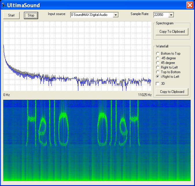
Spectral Analysis of Knock Sound
PC-Based Spectrograph freeware:
http://ultimaserial.com/UltimaSound.html
FFT1024: 1024-point Fast Fourier Transfer (FFT) ActiveX control for spectrum analysis
http://ultimaserial.com/FFT1024.html
For mic input volume control, if needed, feed the Piezo Knock Sensor output to a ±gain stage opamp, and send the signal into the PC mic port.
Here's a couple more freeware FFT tools.
Sonogram Visible Speech 2.41
http://www.download.com/Sonogram-Visibl ... Pid=268503
Sonic Beacon
http://www.download.com/Sonic-beacon/30 ... Pid=483239
Voice Balancing System
http://www.download.com/Voice-Balancing ... id=8316241
FFTToy
http://www.download.com/FFTToy/3000-205 ... d=10860160
- Jim
Re: Knock sensing ideas and circuit designs
Sorry if this has already been covered or the conversation is past this I'm at work and can't read all 6 pages right now.
To incorperate a good knock system into free EMS you only need the knock sensor, or series of sensors to trigger an event, then let the software do the processing on how to "retune" the engine. It can be done in an opposite way to tuning an engine for normal timing and fuel curves with several tables for ignition retard, fuel enrichment, egr percentage, with conditions processed based on coolant temp, tps, map, exaust temp, etc.....
Not difficult to incorperate a basic system but the more time spent on it's flexibility to tune the better it will be.
After reading the posts on the first page or two I think there is some misunderstanding on how knock systems work in an automobile. Knock is not an event that can be timed. It doesn't care when the spark plug fires, it happens because the current engine conditions allow it and therefore the timing when it happens does not matter. What matters is that you change the environment so that it does not happen the next cycle or several cycles. It does not matter what you're current timing is when knock is detected it needs to be retarded, this needs to be tunable since a naturally aspirated engine may only need 2 or 3 degrees of retard to bring it out of knock where a turbo engine may need a lot more. Timing is just one way to reduce knock though. The knock sensor could also be used to inject more fuel or slightly open the EGR valve (if installed) to start reducing combustion temperatures and pull the engine out of knock in the following cycles.An engine will knock after TDC if the conditions dictate, until it has passed the peak pressure point about 30 to 40 degrees down the power stroke you can't really say you are out of the danger zone.
To incorperate a good knock system into free EMS you only need the knock sensor, or series of sensors to trigger an event, then let the software do the processing on how to "retune" the engine. It can be done in an opposite way to tuning an engine for normal timing and fuel curves with several tables for ignition retard, fuel enrichment, egr percentage, with conditions processed based on coolant temp, tps, map, exaust temp, etc.....
Not difficult to incorperate a basic system but the more time spent on it's flexibility to tune the better it will be.
Owner of Mazdatruckin.com