Fred's FreeEMS prototyping hardware thread NO 56K,DSL beware

From DIY contraptions to sophisticated FreeEMS-specific designs! Plus general hardware development!
User avatar
Fred
Moderator
Posts: 15431
Joined: Tue Jan 15, 2008 2:31 pm
Location: Home sweet home!
Contact:

Re: Fred's FreeEMS prototyping hardware thread NO 56K,DSL beware

Post by Fred »

I just gave the MCU about 10mins of solid thrashing. Underneath it is the heatsink on that weak regulator that is so hot i cant touch it, which will be warming the whole board up quite a bit. On top I used dome Bluetak to hold a Ktype thermocouple onto the middle of the chip and let it run. The most I have seen is 53.5C and ambient is 21.3C. The max junction temps for our non-automotively rated 'C' devices is 100C, and max ambient is 85C. I guess the most it is likely to get to by itself is 40C over ambient (without overclocking), so assuming that the junction temp is 15C above case temp, the temperature in our future EMS could get to 45C without issue.

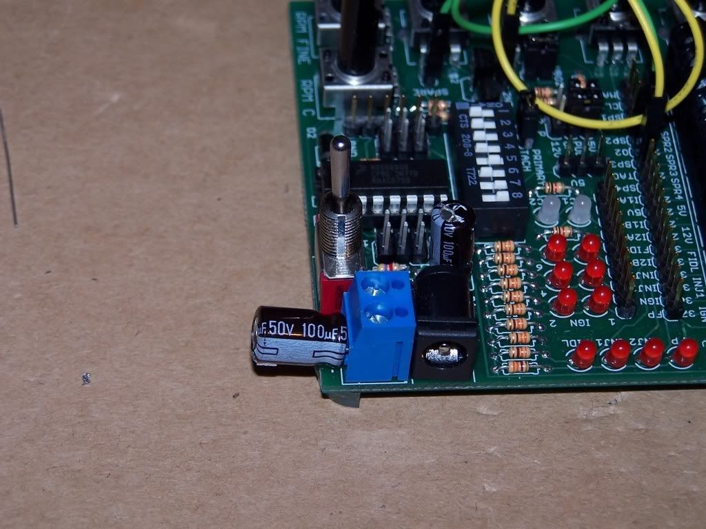
Additionally, when touching just 1/4 of the remaining space with my finger, the temp plummeted, so it would be reasonable to assume that the situation could be improved further with a adhesive heat sink or two designed for ICs stuck to the top of the chip.

In a hot country, 45C inside the case will be quiet easy to reach, so for those people, I would recommend using the stick on sinks. At home in NZ or here, exterior temps never exceed about 30C and with an ally enclosure mounted appropriately the chances of cooking it are slim to none. Also, firing All channels at 99% duty with maxed out current limits on all pins is somewhat worst case. In reality if you are pushing the car that hard for that long, something else like you or it will probably give first :-)

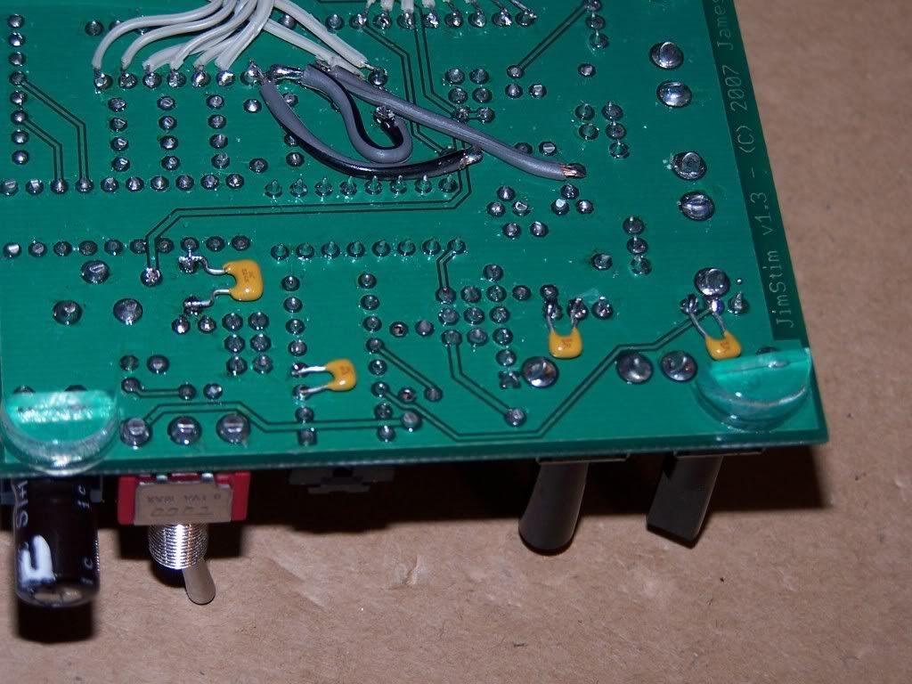
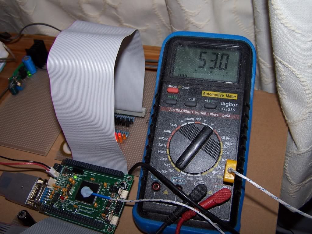
Also, the BlueTak will be insulating the chip, so it would probably be 5C colder without that there. And a bunch colder again without the overstressed reg cooking it slowly from below. This is a nice baseline though to use for when I move the heatsink off to another board. Should be interesting to see how much cooler it runs like that.

With no IC's occurring and NO injector channels being driven, the temperature fell about 4C So by that, the load on the chip doesn't seem to make much difference, more the internal stuff just whirring around continuously generating most of the heat.

Image

Admin.
DIYEFI.org - where Open Source means Open Source, and Free means Freedom
FreeEMS.org - the open source engine management system
FreeEMS dev diary and its comments thread and my turbo truck!
n00bs, do NOT PM or email tech questions! Use the forum!
The ever growing list of FreeEMS success stories!
User avatar
Fred
Moderator
Posts: 15431
Joined: Tue Jan 15, 2008 2:31 pm
Location: Home sweet home!
Contact:

Re: Fred's FreeEMS prototyping hardware thread NO 56K,DSL beware

Post by Fred »

All my stuff is apart and in a big mess right now.

I've removed the reg from the adapt board, and jumpered the in and out pins such that the 2 pin header is now pure 5v instead of 6 - 12. I tried feeding it its 5v through the IDC cable from one side but just sitting doing nothing it dropped 25mV, so I feed it directly from the power board now.

I've also put an lm2940 on the heatsink and mounted it with far too many caps and inductors etc on the power board for feeding the LEDs. The lm2941 is there too, but unsinked and only supplying the CPU. Additionally, I've had to re route all my feeds and grounds to not use the cpu feed.

Lastly, I've put 3 extra 10k B pots on the end of header board 1 so that all ADCs can be used for testing etc.

I'll try to get all this done and posted today, but no promises.

I have the code all in pieces at the moment too doing some major renovations and improvements to structure and features. I will likely leave it that way for a little while and put some work into the site so we can go public. The private factor is severely limiting who can get involved, and I strongly feel that too narrow a group of people having all the say is a bad thing. As it is those who have been vocal have pushed me in the right direction somewhat and at least challenged me to think about why i want what i want. Thats good. More of that from others would be even better, and more of the others vs. others too. So, site = priority for now. If i get any brilliant code ideas while in the shower, i will follow them up at least with a TODO comment etc.

Breakfast!

Admin.
DIYEFI.org - where Open Source means Open Source, and Free means Freedom
FreeEMS.org - the open source engine management system
FreeEMS dev diary and its comments thread and my turbo truck!
n00bs, do NOT PM or email tech questions! Use the forum!
The ever growing list of FreeEMS success stories!
User avatar
Fred
Moderator
Posts: 15431
Joined: Tue Jan 15, 2008 2:31 pm
Location: Home sweet home!
Contact:

Re: Fred's FreeEMS prototyping hardware thread NO 56K,DSL beware

Post by Fred »

Something is funky in my JimStim and h1 board wiring, it causes weird stuff and then the cpu to shut down. I need to look into fixing that. With only h2 hooked up, the temps max at 41, so thats about 15C colder than with the reg baking it from below which is a good if unfair test. Once I sort out the other boards and get it all setup properly again, I'll know more about how it's all working. I suspect that it's a short causing the vreg to constantly reset and then shut down. Will have to find it.
DIYEFI.org - where Open Source means Open Source, and Free means Freedom
FreeEMS.org - the open source engine management system
FreeEMS dev diary and its comments thread and my turbo truck!
n00bs, do NOT PM or email tech questions! Use the forum!
The ever growing list of FreeEMS success stories!
User avatar
Fred
Moderator
Posts: 15431
Joined: Tue Jan 15, 2008 2:31 pm
Location: Home sweet home!
Contact:

Re: Fred's FreeEMS prototyping hardware thread NO 56K,DSL beware

Post by Fred »

Electrical lesson learned :

Capacitive coupling! I had no ground hooked to my input capacitances for wheels and ADCs. The were dragging each other round and screwing up the signals badly. Each input cap should have a separate ground to a central ground point. (star grounding) I know that, but I really didn't think it would be THIS big a deal :-) Makes perfect sense of course, but this could explain some other glitches I was seeing randomly too. I'll have to put some more thought into making it properly right or it could influence my judgment of code correctness etc...
DIYEFI.org - where Open Source means Open Source, and Free means Freedom
FreeEMS.org - the open source engine management system
FreeEMS dev diary and its comments thread and my turbo truck!
n00bs, do NOT PM or email tech questions! Use the forum!
The ever growing list of FreeEMS success stories!
User avatar
Fred
Moderator
Posts: 15431
Joined: Tue Jan 15, 2008 2:31 pm
Location: Home sweet home!
Contact:

Re: Fred's FreeEMS prototyping hardware thread NO 56K,DSL beware

Post by Fred »

OK, I got all the hardware almost sorted out, it all works sweet again with individual grounds etc.

I have some interesting data however :

I installed a 0.35 Ohm resistor in series with the supply to the LM2931 regulator and unplugged both boards so that it is just a CPU, 40MHz PLL, and single LED flashing through a 2k resistor :

LED on 60mV, 171mA : http://www.google.com/search?hl=en&safe ... tnG=Search
LED off 55mV, 157mA : http://www.google.com/search?hl=en&safe ... tnG=Search
Boards plugged in, LEDs all being driven by other power supply, just transistor bias current and switching capacitive load etc :
90mV, 257mA : http://www.google.com/search?hl=en&safe ... tnG=Search

Interesting stuff considering that the regulator is supposed to supply the CPU without a heat sink and is only rated to 100mA in the first place.

I'll flick Carl another email to let him know that it's as good as useless really. I imagine it would draw about 1/3 that much juice without the PLL set, but PLL is the first code you would write really... otherwise you almost may as well have an older slower chip...

So, to all those adapt buying individuals, remove the reg, bridge in and out pins, build external LDO 5V power supply, and feed it in through the 2 pin header.

Admin.
DIYEFI.org - where Open Source means Open Source, and Free means Freedom
FreeEMS.org - the open source engine management system
FreeEMS dev diary and its comments thread and my turbo truck!
n00bs, do NOT PM or email tech questions! Use the forum!
The ever growing list of FreeEMS success stories!
User avatar
Fred
Moderator
Posts: 15431
Joined: Tue Jan 15, 2008 2:31 pm
Location: Home sweet home!
Contact:

Re: Fred's FreeEMS prototyping hardware thread NO 56K,DSL beware

Post by Fred »

http://www.google.com/search?hl=en&q=23 ... eres&meta=

23.5mV = 67mA in bootloader mode with the headers unplugged. I assume bootloader mode is at 16MHz and not 40MHz.

I guess this explains the regulator choice, but I still don't think it's appropriate really.

Even just supplying that and nothing else the regulator is almost too hot to touch.

Admin.
DIYEFI.org - where Open Source means Open Source, and Free means Freedom
FreeEMS.org - the open source engine management system
FreeEMS dev diary and its comments thread and my turbo truck!
n00bs, do NOT PM or email tech questions! Use the forum!
The ever growing list of FreeEMS success stories!
User avatar
Fred
Moderator
Posts: 15431
Joined: Tue Jan 15, 2008 2:31 pm
Location: Home sweet home!
Contact:

Re: Fred's FreeEMS prototyping hardware thread NO 56K,DSL beware

Post by Fred »

Power supply board now with 4 regulators, 2 inductors and many capacitors

Image

Also note the two feeds, one for LEDs and the other for CPU power.

Here you can see the distribution cable that feeds power from one H board to the other.

Image

and here the 3 extra pots :

Image

Also note another 13 LEDs and drivers have been added...

Now serial comms can be monitored too.

All in the name of separate clean power for cpu+adc and dirty power for driven devices. Additionally, the ground returns from the caps on inputs are separate too.

Admin.
DIYEFI.org - where Open Source means Open Source, and Free means Freedom
FreeEMS.org - the open source engine management system
FreeEMS dev diary and its comments thread and my turbo truck!
n00bs, do NOT PM or email tech questions! Use the forum!
The ever growing list of FreeEMS success stories!
User avatar
Fred
Moderator
Posts: 15431
Joined: Tue Jan 15, 2008 2:31 pm
Location: Home sweet home!
Contact:

Re: Fred's FreeEMS prototyping hardware thread NO 56K,DSL beware

Post by Fred »

I found a heatsink to attach to the crappy regulator and have given the whole lot a bit of a soak test.

I'm seeing 40C max case temp on the CPU with a full load. That's 20C over ambient, which with a 15C to core temp difference gives us a max ambient housing temp of 100 - (15 + 20) = 65C which should be plenty for most people. I'll be finding a ram or IC heatsink for mine anyway, just because that's how I am :-)

Touching my fingers on it brings it down a few degrees pretty fast, so a proper heatsink will do much more than that.

On with the site, and then the code.

Admin.
DIYEFI.org - where Open Source means Open Source, and Free means Freedom
FreeEMS.org - the open source engine management system
FreeEMS dev diary and its comments thread and my turbo truck!
n00bs, do NOT PM or email tech questions! Use the forum!
The ever growing list of FreeEMS success stories!
User avatar
Fred
Moderator
Posts: 15431
Joined: Tue Jan 15, 2008 2:31 pm
Location: Home sweet home!
Contact:

Re: Fred's FreeEMS prototyping hardware thread NO 56K,DSL beware

Post by Fred »

I've been doing some testing, and all my input noise was caused by the input caps on the H1 board TC0 and TC1 inputs.
I wrote:Caps on the RPM inputs are a BAD thing apparently. Not only do they combined with the input resistor severely limit RPM, they also severely shorten the pulses, but worse, they do it in an rpm dependent way. I snipped the returns on the two H1 input caps and put bigger caps straight onto the adapt card. that made it worse, not better, so i put smaller ones in, better, took them out, perfect. strange.
This is good in a way, as it gives me a way to generate noise and distortion quite easily to test my decoder when I get around to writing it.

Admin.
DIYEFI.org - where Open Source means Open Source, and Free means Freedom
FreeEMS.org - the open source engine management system
FreeEMS dev diary and its comments thread and my turbo truck!
n00bs, do NOT PM or email tech questions! Use the forum!
The ever growing list of FreeEMS success stories!
User avatar
Fred
Moderator
Posts: 15431
Joined: Tue Jan 15, 2008 2:31 pm
Location: Home sweet home!
Contact:

Re: Fred's FreeEMS prototyping hardware thread NO 56K,DSL beware

Post by Fred »

I decided to try to stabilise the JimStim output by decoupling the two pots and processor and adding a pair of electrolytics to the in and out on the regulator. What a difference. TOTALLY consistent crank pulse count at the FreeEMS now. When the pots are just between two ADC steps, the jitter is much finer and faster.

0.01uF on each pot and on VSS/VDD of the processor
100uF in place of the 0.22uF and the 0.22uF relocated to the bottom of the board.
100uF in the screw block on the corner on the input to the regulator.

pics :

Image

Image

Highly recommended unless you are trying to create dodgy signals for testing :-)

To be fair, it is designed to be plugged in directly to a MegaSquirt, and in that configuration, the grounding would be better/different. But this has improved it for my use no end.

Admin.
DIYEFI.org - where Open Source means Open Source, and Free means Freedom
FreeEMS.org - the open source engine management system
FreeEMS dev diary and its comments thread and my turbo truck!
n00bs, do NOT PM or email tech questions! Use the forum!
The ever growing list of FreeEMS success stories!
Locked