Fred's FreeEMS prototyping hardware thread NO 56K,DSL beware

From DIY contraptions to sophisticated FreeEMS-specific designs! Plus general hardware development!
User avatar
Fred
Moderator
Posts: 15431
Joined: Tue Jan 15, 2008 2:31 pm
Location: Home sweet home!
Contact:

Re: Fred's FreeEMS prototyping hardware thread NO 56K,DSL beware

Post by Fred »

I've been working on tidying up my proto hardware. Here is what I have done :
  • Put a 2.1mm DC power plug on the wire from my PSU board to the JimStim
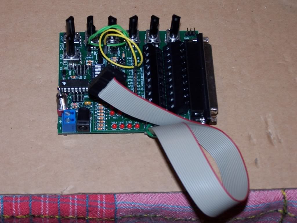
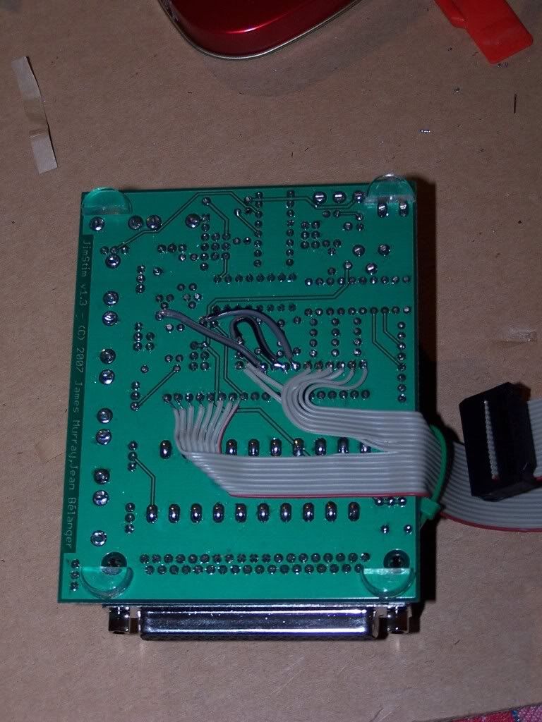
  • Soldered a 16 way IDC cable to the JimStim to carry 2 x "tach" pulses, 6 x "ign LED", 2 x 5v, 5 x ADC pots, 1 x spare goes to ADC
  • Added a socket for that on the H1 proto card and wired that to the appropriate MCU pins via buffer circuits (8 x PWM, 2 x ECT, existing ADC inputs)
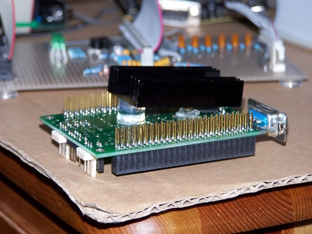
  • Soldered a header to the H2 board
  • Added four rubber feet to each of the four external boards
And here are the pics :

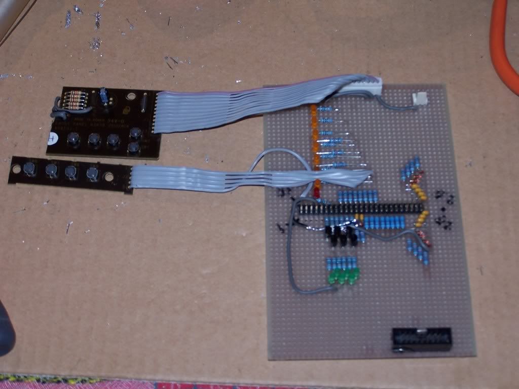
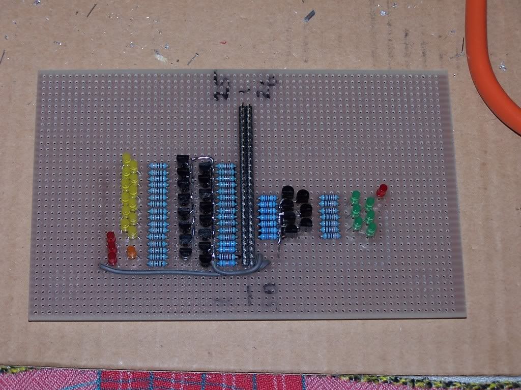
Additional circuits :

Image

Image

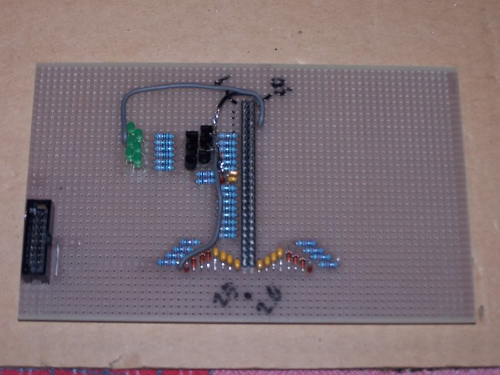
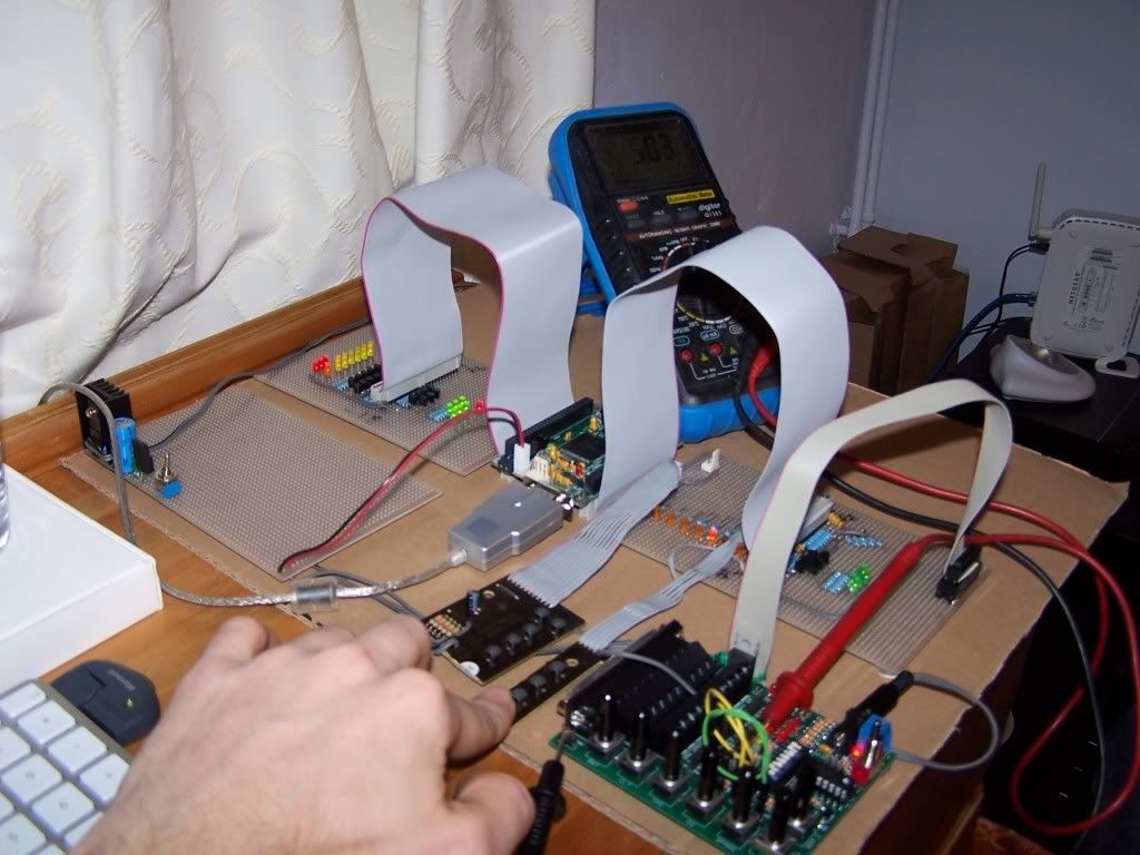
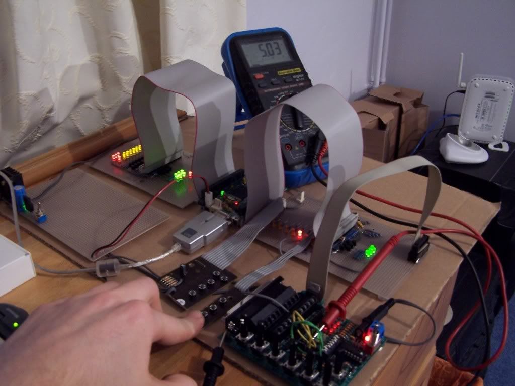
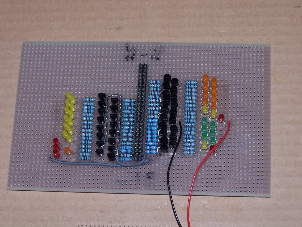
JimStim ribbon complete (note "IAC" LEDs are wired, one in each polarity, to the two "tach" signals) :

Image

Image

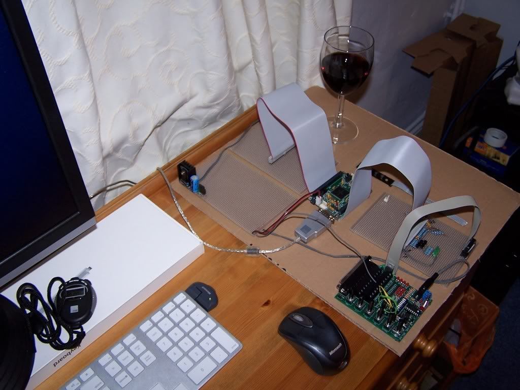
Here it is all together with the most important, a glass of good red wine! :

Image

Thats over a quarter of the pins brought out to circuits now :-)

Admin.
DIYEFI.org - where Open Source means Open Source, and Free means Freedom
FreeEMS.org - the open source engine management system
FreeEMS dev diary and its comments thread and my turbo truck!
n00bs, do NOT PM or email tech questions! Use the forum!
The ever growing list of FreeEMS success stories!
User avatar
Fred
Moderator
Posts: 15431
Joined: Tue Jan 15, 2008 2:31 pm
Location: Home sweet home!
Contact:

Re: Fred's FreeEMS prototyping hardware thread NO 56K,DSL beware

Post by Fred »

Here is that gear in action with some slightly updated code :

http://www.youtube.com/watch?v=B8pV3oLazr8

Admin.
DIYEFI.org - where Open Source means Open Source, and Free means Freedom
FreeEMS.org - the open source engine management system
FreeEMS dev diary and its comments thread and my turbo truck!
n00bs, do NOT PM or email tech questions! Use the forum!
The ever growing list of FreeEMS success stories!
User avatar
Fred
Moderator
Posts: 15431
Joined: Tue Jan 15, 2008 2:31 pm
Location: Home sweet home!
Contact:

Re: Fred's FreeEMS prototyping hardware thread NO 56K,DSL beware

Post by Fred »

This morning I have determined a number of things :

One :

The 330 Ohm resistors I have been using in place of the 1k ones that I ordered and did not receive are not OK. They drop 3.64V each while in the on state into a 2n3904 base with a 330 Ohm LED current limiting resistor which is only dropping 3.0V at the same time.

V=IR
3.64 = I * 330
I = 3.64/330
I = 11mA

Which is WAY too much. In fact, I'd go so far as to say that it's fairly impressive that it hasn't died and will drive 16 channels on two ports solid on for about 10 seconds before the processor locks up!

After desoldering 23 of them, I stuck a 10k back in and measured it. The same 3.0V was present across the LED current limiting resistor, and 4.1V across the 10k from the processor pin.

Which of course works out to 0.41mA which is definitely low enough.

...several hours go by...

I read up in the dirtiest most detailed parts of the data sheet for it, and found that they test the pins at 4mA each. I also recall reading that each port can handle a max of 25mA total. Based on this and the intended possible voltage drop of the output, I settled on two values for buffers from the MCU to the world. 1.2k for the 6 main fuel channels and the 12 ignition channels (only if they will be used in this way), and 1.6k for all other drive pins. All resistors are installed and the MCU is no longer locking up etc.

Two :

I've been told and read in the past that the SM trigger pin can not be used in code as an output. I now suspect that the hardware used by those that said that port can not be used (MS2) is not configured correctly (surprise surprise), and that provided that a suitably strong pullup is used relative to the output current limiting resistor it should work fine. The only possible exception to this would be if the reset occured VERY fast and the internal capacitance was too great to be overcome quickly enough by the pull up. I've settled on a pull up of 1.6k and a limiting resistor of 5k because thats what I had around. I would suggest going to 1.2k for the pull up, and as high a value as you can manage for the series resistor to minimise the chance of an issue occurring.

I'll be configuring that port to alternate on and off periodically and leaving it like that until we need a spare port to use. that way any resets have a 50/50 chance of occurring with it on or off and we will see if it's an issue or not.

Time to do a bit more soldering and slicing and then cook dinner. I doubt I'll have any interrupt code running tonight, but you never know.

Admin.
DIYEFI.org - where Open Source means Open Source, and Free means Freedom
FreeEMS.org - the open source engine management system
FreeEMS dev diary and its comments thread and my turbo truck!
n00bs, do NOT PM or email tech questions! Use the forum!
The ever growing list of FreeEMS success stories!
User avatar
Fred
Moderator
Posts: 15431
Joined: Tue Jan 15, 2008 2:31 pm
Location: Home sweet home!
Contact:

Re: Fred's FreeEMS prototyping hardware thread NO 56K,DSL beware

Post by Fred »

Here is today and yesterdays list of solder based achievements :

Added 9 tactile switches and indicator LEDs
Added 12 ignition LEDs
Added 5 GPIO LEDs
Added 6 staged injection LEDs
Replaced all current limiting resistors with appropriate values
Added DPDT switch for killing 5v and 12v supply to the rig.

photos :

H1 baord :

Image

Image

H2 board :

Image

Image

Full rig on and lights flashing brightly (with and without flash) :

Image

Image

each LED circuit consists of 4 components each of which has 2 legs or more = 8 solder joints
each component requires the trace to be cut between it's legs, each cut requires 4 incisions with the craft knife.

approximately :
40x4X2 + 40x2 or so solder joints so far = 400 solder joints
800 cuts to the board with my nice NTCutter Japanese made knife (highly recommended)

here are most of the pigtails :

Image

Man I love soldering :-) GO DIY EFI!!

Here you can see things flashing in action :

http://www.youtube.com/watch?v=MoQdrLiS-tI

Of course now a new problem has cropped up, the 5V regulator can't handle the current being passed through it and is cycling on and off with overheat... I'll rectify that tomorrow probably.

Enjoy,

Admin
DIYEFI.org - where Open Source means Open Source, and Free means Freedom
FreeEMS.org - the open source engine management system
FreeEMS dev diary and its comments thread and my turbo truck!
n00bs, do NOT PM or email tech questions! Use the forum!
The ever growing list of FreeEMS success stories!
User avatar
Fred
Moderator
Posts: 15431
Joined: Tue Jan 15, 2008 2:31 pm
Location: Home sweet home!
Contact:

Re: Fred's FreeEMS prototyping hardware thread NO 56K,DSL beware

Post by Fred »

The part numbers on the regulator are the following (recorded here so I don't have to bend the legs again and risk them snapping) :

JC75RA
LM2931
AT5.0

And it's about to get a decent sized heat sink hung off it for powering all those LEDs

Admin.
DIYEFI.org - where Open Source means Open Source, and Free means Freedom
FreeEMS.org - the open source engine management system
FreeEMS dev diary and its comments thread and my turbo truck!
n00bs, do NOT PM or email tech questions! Use the forum!
The ever growing list of FreeEMS success stories!
User avatar
Fred
Moderator
Posts: 15431
Joined: Tue Jan 15, 2008 2:31 pm
Location: Home sweet home!
Contact:

Re: Fred's FreeEMS prototyping hardware thread NO 56K,DSL beware

Post by Fred »

The regulator resetting issue is fixed, but the reg is still running pretty hot (can touch it, but holding it for more than 10 - 20 seconds is interesting). The CPU on the other hand is still just luke warm which is good. It's pushing out about 4x13 mA plus whatever the core draws. The LED's are soaking up about 2.5x that again, so the sum is probably around 300mA or so.

Image

Image

Image

Image

Either way, it's been running for a few hours now with no issues, and a real application won't have to push that current at all. just the cpu and ADC and they will have a regulator each anyway.

Admin.
DIYEFI.org - where Open Source means Open Source, and Free means Freedom
FreeEMS.org - the open source engine management system
FreeEMS dev diary and its comments thread and my turbo truck!
n00bs, do NOT PM or email tech questions! Use the forum!
The ever growing list of FreeEMS success stories!
User avatar
Fred
Moderator
Posts: 15431
Joined: Tue Jan 15, 2008 2:31 pm
Location: Home sweet home!
Contact:

Re: Fred's FreeEMS prototyping hardware thread NO 56K,DSL beware

Post by Fred »

Todays update includes no stills, but rather a video. The video demonstrates the test rigs new found ability to make noise :-)

The piezo is hooked to the tach output and can be heard in person up to 10kHz however the mic on my camera doesn't go that high apparently...

http://www.youtube.com/watch?v=vkATvZ473lM

This serves as an audible rate indicator (because the leds become a blur pretty quickly) and also to remind me to turn it off and avoid causing another fire from the old phone adapter thats powering it :-)

The dual ADC input code that you need to get a nice frequency sweep is available here :

http://sourceforge.net/project/showfile ... _id=579196

This thread is likely to be pretty quiet for a while now. I have enough I/O configured to test a V12 with COP, bit banged 12 cyl sequential or 6 way semi and 6 way staged + fuel pump + tacho + status outputs and a bunch of ADC inputs and interrupt inputs.

I still have input conditioning circuits to build for the other 8 ADCs and VR conditioners and more transistor buffers on the pwm outputs etc. I'll post here if/when I get around to those (probably quite a bit further down the firmware line) or when I receive a very kindly donated FPGA demo board from someone that wants their business plugged on here :-)

Admin.
DIYEFI.org - where Open Source means Open Source, and Free means Freedom
FreeEMS.org - the open source engine management system
FreeEMS dev diary and its comments thread and my turbo truck!
n00bs, do NOT PM or email tech questions! Use the forum!
The ever growing list of FreeEMS success stories!
User avatar
Fred
Moderator
Posts: 15431
Joined: Tue Jan 15, 2008 2:31 pm
Location: Home sweet home!
Contact:

Re: Fred's FreeEMS prototyping hardware thread NO 56K,DSL beware

Post by Fred »

Admin wrote:This thread is likely to be pretty quiet for a while now. I have enough I/O configured to test a V12 with COP, bit banged 12 cyl sequential or 6 way semi and 6 way staged + fuel pump + tacho + status outputs and a bunch of ADC inputs and interrupt inputs.
I spoke too soon...

I built another 12 LED drivers so I can watch 8 bit binary numbers raw for diagnosis reasons, and mimic the JimStim inputs on the two yellow ones in the middle of the right side :

Image

I was also scratching my head over why an ATD wasn't showing any reading at all so stuck a meter into the board and found that when the pots where at 5V the board was at exactly 4V with a 10k input resistor. Strange. Tried turning on the pullup resistor but that just stopped it from going to zero volts too. bridged out the 10k resistor, also no joy. Lifted the 5.1V Zener and bugger me, it came right. How irritating, last time I checked, Zeners were supposed to switch AT their designated voltage... So it looks like careful testing of your particular stock of Zeners is required to ensure its not meddling with your readings and IS protecting the port from damage.

Onward and upward, back to the code face.

Admin.
DIYEFI.org - where Open Source means Open Source, and Free means Freedom
FreeEMS.org - the open source engine management system
FreeEMS dev diary and its comments thread and my turbo truck!
n00bs, do NOT PM or email tech questions! Use the forum!
The ever growing list of FreeEMS success stories!
User avatar
Fred
Moderator
Posts: 15431
Joined: Tue Jan 15, 2008 2:31 pm
Location: Home sweet home!
Contact:

Re: Fred's FreeEMS prototyping hardware thread NO 56K,DSL beware

Post by Fred »

Having progressed far enough in the code to make some progress and turn on 12 fuel channels with 100% duty. i found my cpu resetting!

4.3v is not enough :-)

Apparently I need a more powerful 5v supply to drive the LEDs with. I was going to do it anyway. but testing will be more difficult if I don't do something about it soon.

Admin.
DIYEFI.org - where Open Source means Open Source, and Free means Freedom
FreeEMS.org - the open source engine management system
FreeEMS dev diary and its comments thread and my turbo truck!
n00bs, do NOT PM or email tech questions! Use the forum!
The ever growing list of FreeEMS success stories!
User avatar
Fred
Moderator
Posts: 15431
Joined: Tue Jan 15, 2008 2:31 pm
Location: Home sweet home!
Contact:

Re: Fred's FreeEMS prototyping hardware thread NO 56K,DSL beware

Post by Fred »

I emailed Carl at Tech Art :
Hi Carl,

I've discovered that the on board reg is a bit on the weak side. What
I would like to know is if it's OK to feed the LDO 5v supply back up
through the two 50 pin headers from the board we plug it into? This
would have several advantages :
A the 16V tantalum wouldn't need replacing for auto use
B the existing reg could be cut off as it is physically not suitable
for vibration just hanging by its leads
C the ADC reference voltage would be the same one used by the sensors
rather than from a separate supply
D the reg could be properly heat sinked
E potential high voltages would be kept well clear of the board
etc.

Having looked over the schematic you sent, I can't see any issues with
that, but I thought I'd check to ensure it was OK and that the track
widths could stand the 350mA that the CPU can draw under heavy load. I
imagine so, as it's not much, but better safe than sorry :-) .... <snip>
And his reply was :
Carl wrote:Hi Fred,

Your proposal looks sound. I don't foresee any problems.

Thanks for the links-- I'll add them to the product's web page when I
get a chance.

Looks like you've been very busy-- keep up the great work!

Best regards,
Carl Barnes
So, I might see about installing the lm2940 that I ordered just for this purpose on the spare board and feeding the "reg removed" adapt card from the bottom as I suggested. Any comments on that plan of attack?

I haven't decided on cutting the reg leads, or desoldering it yet, any suggestions with reasons?

Admin.
DIYEFI.org - where Open Source means Open Source, and Free means Freedom
FreeEMS.org - the open source engine management system
FreeEMS dev diary and its comments thread and my turbo truck!
n00bs, do NOT PM or email tech questions! Use the forum!
The ever growing list of FreeEMS success stories!
Locked