
As of this evening I am the proud owner of a spare ECU for the girlfriends car. Once it arrives I'll be ensuring that it is compatible, checking that it works and beginning modifications for the purposes of data-logging the OEM tune and eventually running it in fuel only mode. Ignition can come later after a bunch of other work is complete.
I'm pretty excited about this as it means something to post up about on other boards that will generate further interest. It also means that I'll have something to show for a lot of work that I've done :-) Pretty cool really!
More in this thread when it arrives, and possibly a new thread about modifications to it etc.
Just had to share!
Fred.
OEM ECU for test mule purchased :-)
OEM ECU for test mule purchased :-)
DIYEFI.org - where Open Source means Open Source, and Free means Freedom
FreeEMS.org - the open source engine management system
FreeEMS dev diary and its comments thread and my turbo truck!
n00bs, do NOT PM or email tech questions! Use the forum!
The ever growing list of FreeEMS success stories!
FreeEMS.org - the open source engine management system
FreeEMS dev diary and its comments thread and my turbo truck!
n00bs, do NOT PM or email tech questions! Use the forum!
The ever growing list of FreeEMS success stories!
Re: OEM ECU for test mule purchased :-)
I've assembled some components together to integrate the CPU card with the existing ECU
So far :
The second go will have me controlling the injectors as outputs. This will be how it stays for some time as the code develops and matures.
The third go will be when fuel is stable and usable and I've written some functional (as opposed to the current dysfunctional) ignition code.
So, there you have it, pictures will be posted when there is more to say :-)
Fred.
So far :
- Two LEDs and drivers for echoing the RPM input on an output pair
- Two LEDs and drivers for displaying what I would be doing with the ignition channels (eventually)
- Four LEDs, input resistors, FETs for driving four injectors
- Two 50 pin sockets
- A set of capacitors and a diode for power input
- Six resistors to interface with the ECU and a twelve diodes to protect the CPU.
- Two 10k resistors, one capacitor for battery sensing
- Some ribbon cable to interface the boards
- A 39k resistor for the battery input sensor
- One regulator and thermal pad
- PCB standoffs for mounting the contraption inside the OEM case
- A proto board to build it all on
- A 2 pin connector to feed power to the board
- MAP
- TPS
- Air Temp
- Water Temp
- Battery reference voltage
- RPM main
- RPM secondary
- Injector PW and timing 1 - 4
- Ignition dwell and timing dizzy
The second go will have me controlling the injectors as outputs. This will be how it stays for some time as the code develops and matures.
The third go will be when fuel is stable and usable and I've written some functional (as opposed to the current dysfunctional) ignition code.
So, there you have it, pictures will be posted when there is more to say :-)
Fred.
DIYEFI.org - where Open Source means Open Source, and Free means Freedom
FreeEMS.org - the open source engine management system
FreeEMS dev diary and its comments thread and my turbo truck!
n00bs, do NOT PM or email tech questions! Use the forum!
The ever growing list of FreeEMS success stories!
FreeEMS.org - the open source engine management system
FreeEMS dev diary and its comments thread and my turbo truck!
n00bs, do NOT PM or email tech questions! Use the forum!
The ever growing list of FreeEMS success stories!
Re: OEM ECU for test mule purchased :-)
Bump for revised plan with only 3 stages an a lot more connections for the initial attempt. See the bottom half of the previous post for details.
Fred.
Fred.
DIYEFI.org - where Open Source means Open Source, and Free means Freedom
FreeEMS.org - the open source engine management system
FreeEMS dev diary and its comments thread and my turbo truck!
n00bs, do NOT PM or email tech questions! Use the forum!
The ever growing list of FreeEMS success stories!
FreeEMS.org - the open source engine management system
FreeEMS dev diary and its comments thread and my turbo truck!
n00bs, do NOT PM or email tech questions! Use the forum!
The ever growing list of FreeEMS success stories!
Re: OEM ECU for test mule purchased :-)
I got an email this morning. It said that my package would arrive soon. It was a bit of a waste of time as the package had already arrived. You know the internet is going down hill when snail mail moves faster than email! Awesome service from the seller though! :-)
(non-worthwhile) pics a little later.
Fred.
(non-worthwhile) pics a little later.
Fred.
DIYEFI.org - where Open Source means Open Source, and Free means Freedom
FreeEMS.org - the open source engine management system
FreeEMS dev diary and its comments thread and my turbo truck!
n00bs, do NOT PM or email tech questions! Use the forum!
The ever growing list of FreeEMS success stories!
FreeEMS.org - the open source engine management system
FreeEMS dev diary and its comments thread and my turbo truck!
n00bs, do NOT PM or email tech questions! Use the forum!
The ever growing list of FreeEMS success stories!
Re: OEM ECU for test mule purchased :-)
I've made a little start on modifying the ECU I bought :
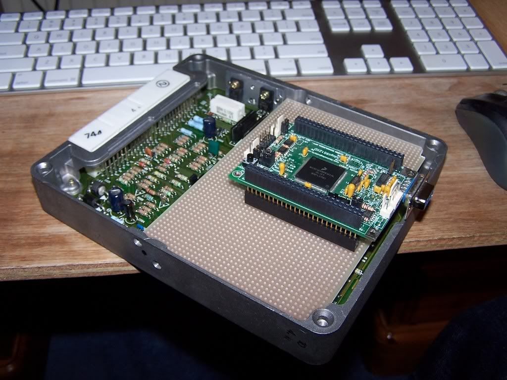
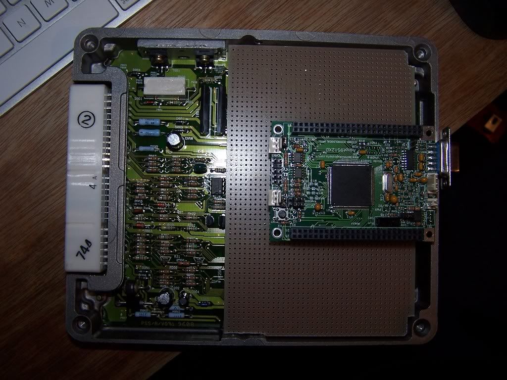
Just a teaser for now, I have some other things to do before I get seriously stuck into that. For a start, I need to find out why it won't start on this ECU and sort that. It is alive because if you bridge E1 and TE1 it flashes continuously which indicates "no fault found". I just need to sort out why it's misbehaving. Probably some switch like an auto in park switch or something missing.
Fred.
DIYEFI.org - where Open Source means Open Source, and Free means Freedom
FreeEMS.org - the open source engine management system
FreeEMS dev diary and its comments thread and my turbo truck!
n00bs, do NOT PM or email tech questions! Use the forum!
The ever growing list of FreeEMS success stories!
FreeEMS.org - the open source engine management system
FreeEMS dev diary and its comments thread and my turbo truck!
n00bs, do NOT PM or email tech questions! Use the forum!
The ever growing list of FreeEMS success stories!
-
SleepyKeys

- LQFP144 - On Top Of The Game
- Posts: 549
- Joined: Mon Feb 11, 2008 10:52 pm
- Location: Arizona
- Contact:
Re: OEM ECU for test mule purchased :-)
VERY SLICK, I will be taking the same approach with my Camaro.
You snooze, you lose!
Re: OEM ECU for test mule purchased :-)
I was searching around to find out what these two random pins meant...
IMI and IMO
...IM stands for Immobiliser and I/O the usual...
Quite possibly I will have to take full control straight out unless I can convince the good woman to let me attach my stuff to her PCB and log that one before trying to run it with this one.
There may be a way around it yet. I haven't asked around and searched etc. If not though, I may have bought a dud :-)
http://www.google.com/patents?id=1wIGAA ... mi+imo+ecu
http://www.google.com/patents?id=Lq8DAA ... mi+imo+ecu
Fred.
DIYEFI.org - where Open Source means Open Source, and Free means Freedom
FreeEMS.org - the open source engine management system
FreeEMS dev diary and its comments thread and my turbo truck!
n00bs, do NOT PM or email tech questions! Use the forum!
The ever growing list of FreeEMS success stories!
FreeEMS.org - the open source engine management system
FreeEMS dev diary and its comments thread and my turbo truck!
n00bs, do NOT PM or email tech questions! Use the forum!
The ever growing list of FreeEMS success stories!
Re: OEM ECU for test mule purchased :-)
Actually, it says that it only performs this code swap after the engine reaches 500 RPM. I'm pretty sure it never got that high, but I'd have to check again to be certain.
DIYEFI.org - where Open Source means Open Source, and Free means Freedom
FreeEMS.org - the open source engine management system
FreeEMS dev diary and its comments thread and my turbo truck!
n00bs, do NOT PM or email tech questions! Use the forum!
The ever growing list of FreeEMS success stories!
FreeEMS.org - the open source engine management system
FreeEMS dev diary and its comments thread and my turbo truck!
n00bs, do NOT PM or email tech questions! Use the forum!
The ever growing list of FreeEMS success stories!
Re: OEM ECU for test mule purchased :-)
Pin out for this particular ECU :
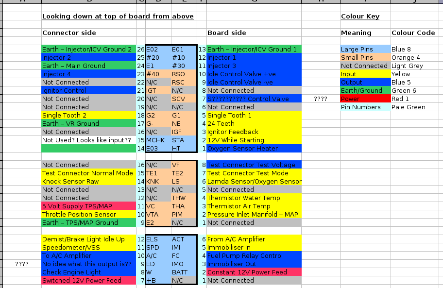
Taken from the ECU labeled with this Toyota part number : 89661-05100
The one with the partnumber 89661-05030 is very very similar to this, if not exactly the same. Yet to find the difference anyway.
It's from a 1996 Toyota Carina E which is the same as a 96 Toyota Corona at home.
The engine is 7a-fe and has a distributor not wasted spark as some 7afe power plants have.
Below is the text from the table small so it can be searched for readily.
Fred.
Looking down at top of board from above
Connector side Board side
Earth – Injector/ICV Ground 2 26 E02 E01 13 Earth – Injector/ICV Ground 1
Injector 2 25 #20 #10 12 Injector 1
Earth – Main Ground 24 E1 #30 11 Injector 3
Injector 4 23 #40 RSO 10 Idle Control Valve +ve
Not Connected 22 N/C RSC 9 Idle Control Valve -ve
Ignitor Control 21 IGT N/C 8 Not Connected
Not Connected 20 N/C SCV 7 S?????????? Control Valve
Not Connected 19 N/C N/C 6 Not Connected
Single Tooth 2 18 G2 G1 5 Single Tooth 1
Earth – VR Ground 17 G- NE 4 24 Teeth
Not Connected 16 N/C IGF 3 Ignitor Feedback
Not Used? Looks like input?? 15 MCHK STA 2 12V While Starting
14 E03 HT 1 Oxygen Sensor Heater
Not Connected 16 N/C VF 8 Test Connector Test Voltage
Test Connector Normal Mode 15 TE1 TE2 7 Test Connector Test Mode
Knock Sensor Raw 14 KNK LS 6 Lamda Sensor/Oxygen Sensor
Not Connected 13 N/C N/C 5 Not Connected
Not Connected 12 N/C THW 4 Thermistor Water Temp
5 Volt Supply TPS/MAP 11 VC THA 3 Thermistor Air Temp
Throttle Position Sensor 10 VTA PIM 2 Pressure Inlet Manifold – MAP
Earth – TPS/MAP Ground 9 E2 N/C 1 Not Connected
Demist/Brake Light Idle Up 12 ELS ACT 6 From A/C Amplifier
Speedometer/VSS 11 SPD IMI 5 Immobiliser In
To A/C Amplifier 10 A/C FC 4 Fuel Pump Relay Control
No idea what this output is?? 9 ED IMO 3 Immobiliser Out
Check Engine Light 8 W BATT 2 Constant 12V Power Feed
Switched 12V Power Feed 7 +B N/C 1 Not Connected
DIYEFI.org - where Open Source means Open Source, and Free means Freedom
FreeEMS.org - the open source engine management system
FreeEMS dev diary and its comments thread and my turbo truck!
n00bs, do NOT PM or email tech questions! Use the forum!
The ever growing list of FreeEMS success stories!
FreeEMS.org - the open source engine management system
FreeEMS dev diary and its comments thread and my turbo truck!
n00bs, do NOT PM or email tech questions! Use the forum!
The ever growing list of FreeEMS success stories!