
Hi, I thought this deserves it's own thread because there are a few ways that this could work, and a few aspects them.
At the top of the food chain there is the battery. This is closely followed by a relay that is controlled by the ignition key. That relay supplies anything that only needs to be on when the key is on. From there on out there are a few things that need doing.
Firstly, we need to control the fuel pump for safety reasons, and later for wear and tear and fuel pressure consistency reasons with PWM. We'll focus on relay control of it for now as my pump for example draws 16 Amps during normal running at higher pressures and therefore probably a whole lot more at turn on time during PWM.
Secondly we have the injectors and coils needing a power supply, I can't think of any reason to not power these A together, B with the fuel pump, can you?
Thirdly there is desire from a number of people including myself to have the ECU at the least, keep itself on after the key goes off to allow time to save data. This probably requires 1 input (from key/key relay) and 1 output to control it's own power supply. Instead of that, I would prefer to allow power to run to the unit continuously and just have one input that monitors key and causes the unit to go into sleep after saving data and come out of sleep when a signal is applied to it.
So, as I see it we need the following :
1 input from the key or key relay
1 output to the fuel pump, injectors, coils to prevent them burning during a firmware upgrade without great complexity.
1 constant 5V feed to the CPU
1 switched 5V feed to the sensors
The fuel pump relay could draw it's power from the key relay such that you need (KEY_ON && ECU_FP_OUT_ON) to get any juice to any of those critical components.
Having the EMS turn itself off one way or another has a lot of benefits. For example, you could use it to power an electric water pump and keep coolant circulating through the engine after shut down. Ditto for the oil system to stop the turbo from coking up. Storing of last shutdown time and conditions for better cold starting and hot starting performance and heat soak knowledge for the MAT and IAT sensors. Possibly other things I haven't thought of.
Can anyone see a problem with this, a better way of doing it, something I have forgotten etc?
If we do it this way we only burn one pin. If we place control of the ECU's own power in it's own hands we burn 2 pins and add extra complexity.
Thoughts?
Fred.
Power control of the EMS system
Power control of the EMS system
DIYEFI.org - where Open Source means Open Source, and Free means Freedom
FreeEMS.org - the open source engine management system
FreeEMS dev diary and its comments thread and my turbo truck!
n00bs, do NOT PM or email tech questions! Use the forum!
The ever growing list of FreeEMS success stories!
FreeEMS.org - the open source engine management system
FreeEMS dev diary and its comments thread and my turbo truck!
n00bs, do NOT PM or email tech questions! Use the forum!
The ever growing list of FreeEMS success stories!
-
davebmw
- LQFP144 - On Top Of The Game
- Posts: 331
- Joined: Sun Jul 13, 2008 2:58 pm
- Location: South Wales, UK
Re: Power control of the EMS system
i think:
1 pin would be sufficient to activate the fuel pump relay, saves complexity.
the main relay should be controlled by the ignition key and supply power to coils, injectors and O2 controller.
the ECU should have permanent supply to carry out its controlled shutdown sequence, could also later be used for turbo timer function etc.
The ECU should ideally monitor the ignition line to bring it out of sleep mode. but i guess thats a second pin.
IMO that would cover the bases.
93'BMW 325is M50B25TU, Rebuilt 06/06, JE10.5:1, polish&port. Scorpion BB, K&N CAI, TEJ21 WBO2, '07 M3 Evo 18" 225F, 255R, EBC Kevlar, Bilstien Sprint, Polyflex. Head rebuild Oct'08, OEM+FSE FPR, MS2v3.0_DJB Custom, Extra 2.0.1
-
gearhead
- LQFP112 - Up with the play
- Posts: 120
- Joined: Sun Feb 03, 2008 9:30 pm
- Location: Chicago, USA
Re: Power control of the EMS system
This is how mine was set from the factory with a Bosch LH injection system.Fred wrote:Hi, I thought this deserves it's own thread because there are a few ways that this could work, and a few aspects them.
At the top of the food chain there is the battery. This is closely followed by a relay that is controlled by the ignition key. That relay supplies anything that only needs to be on when the key is on. From there on out there are a few things that need doing.
Firstly, we need to control the fuel pump for safety reasons, and later for wear and tear and fuel pressure consistency reasons with PWM. We'll focus on relay control of it for now as my pump for example draws 16 Amps during normal running at higher pressures and therefore probably a whole lot more at turn on time during PWM.
Secondly we have the injectors and coils needing a power supply, I can't think of any reason to not power these A together, B with the fuel pump, can you?
http://ys3al35l.googlepages.com/lh24wiringNFMP.gif
ECU is powered on from the key at pin 35
The fuel pump needs to be on and pressurize system - cycles for 2 s at key on and is on when there is a crank pulse - relay 102
The injectors, ELCD and IAC (and ignition in my case, now) are powered by the relay number 229.
I like this way of doing things even though it burns an output pin. It allows the unit to shut down power as well as ground to the devices under its control. I can be talked out of it and it is not absolutely necessary as I have been running with these being turned on by the fuel pump relay output on both MS1/E and MS2/E since it gets to be 'on' as soon as it sees a crank signal.
I like the idea of the unit having a memory. If that is from a 3V battery or from the 12V, I am fine with it. What this persistence allows us to do in the future is perform some sort of learning (like EECIV and Trionic). I am not as interested in having the unit flash some tuning data after key off as I am in persistent flash memory for some sort of learning capability. If it burns another pin for that, it is a negative. I do not mind burning a pin for the control of the +12 to the injectors/ignition, but am not religiously bound to this concept.Fred wrote: Thirdly there is desire from a number of people including myself to have the ECU at the least, keep itself on after the key goes off to allow time to save data. This probably requires 1 input (from key/key relay) and 1 output to control it's own power supply. Instead of that, I would prefer to allow power to run to the unit continuously and just have one input that monitors key and causes the unit to go into sleep after saving data and come out of sleep when a signal is applied to it.
So, as I see it we need the following :
1 input from the key or key relay
1 output to the fuel pump, injectors, coils to prevent them burning during a firmware upgrade without great complexity.
1 constant 5V feed to the CPU
1 switched 5V feed to the sensors
The fuel pump relay could draw it's power from the key relay such that you need (KEY_ON && ECU_FP_OUT_ON) to get any juice to any of those critical components.
Having the EMS turn itself off one way or another has a lot of benefits. For example, you could use it to power an electric water pump and keep coolant circulating through the engine after shut down. Ditto for the oil system to stop the turbo from coking up. Storing of last shutdown time and conditions for better cold starting and hot starting performance and heat soak knowledge for the MAT and IAT sensors. Possibly other things I haven't thought of.
Can anyone see a problem with this, a better way of doing it, something I have forgotten etc?
If we do it this way we only burn one pin. If we place control of the ECU's own power in it's own hands we burn 2 pins and add extra complexity.
Thoughts?
Fred.
Gearhead
Re: Power control of the EMS system
I can only see one single benefit to controlling the coils and injectors + feed from the EMS and that is to stop flooding and burnt coils during firmware upgrades. We can setup the transistor for relay control such that it is off when the bootloader is running (different pins are in different states during this time) and thus no one will fry their coils and hydraulic their engines as regularly happens with MS systems.
I see no benefit to separate control of coils/injectors and fuel pump. Can you show me what it is? If so, keen to understand.
Fred.
I see no benefit to separate control of coils/injectors and fuel pump. Can you show me what it is? If so, keen to understand.
Fred.
DIYEFI.org - where Open Source means Open Source, and Free means Freedom
FreeEMS.org - the open source engine management system
FreeEMS dev diary and its comments thread and my turbo truck!
n00bs, do NOT PM or email tech questions! Use the forum!
The ever growing list of FreeEMS success stories!
FreeEMS.org - the open source engine management system
FreeEMS dev diary and its comments thread and my turbo truck!
n00bs, do NOT PM or email tech questions! Use the forum!
The ever growing list of FreeEMS success stories!
-
gearhead
- LQFP112 - Up with the play
- Posts: 120
- Joined: Sun Feb 03, 2008 9:30 pm
- Location: Chicago, USA
Re: Power control of the EMS system
Coil and injector feed needs to be separate from the fuel pump feed due to the time difference between when the pressure needs to be available and when the injectors need to open up. Is it critical, no. Like I said, it works as is with all of them commanded by the FPR relay control on my MS system.Fred wrote:I can only see one single benefit to controlling the coils and injectors + feed from the EMS and that is to stop flooding and burnt coils during firmware upgrades. We can setup the transistor for relay control such that it is off when the bootloader is running (different pins are in different states during this time) and thus no one will fry their coils and hydraulic their engines as regularly happens with MS systems.
I see no benefit to separate control of coils/injectors and fuel pump. Can you show me what it is? If so, keen to understand.
Fred.
Gearhead
Re: Power control of the EMS system
I don't see that need. They don't need to be on, but they don't need to be off either. There is no benefit in having them off as far as I can tell. Is there a benefit to having them off when they could be? I don't think so, but I could be wrong. If there is a tangible reason for not allowing them to have power when the pump does, by all means put me straight.gearhead wrote:Coil and injector feed needs to be separate from the fuel pump feed due to the time difference between when the pressure needs to be available and when the injectors need to open up. Is it critical, no. Like I said, it works as is with all of them commanded by the FPR relay control on my MS system.
Fred.
DIYEFI.org - where Open Source means Open Source, and Free means Freedom
FreeEMS.org - the open source engine management system
FreeEMS dev diary and its comments thread and my turbo truck!
n00bs, do NOT PM or email tech questions! Use the forum!
The ever growing list of FreeEMS success stories!
FreeEMS.org - the open source engine management system
FreeEMS dev diary and its comments thread and my turbo truck!
n00bs, do NOT PM or email tech questions! Use the forum!
The ever growing list of FreeEMS success stories!
Re: Power control of the EMS system
Ta da!
EDIT : See the next page instead of this : http://i260.photobucket.com/albums/ii15 ... wiring.png
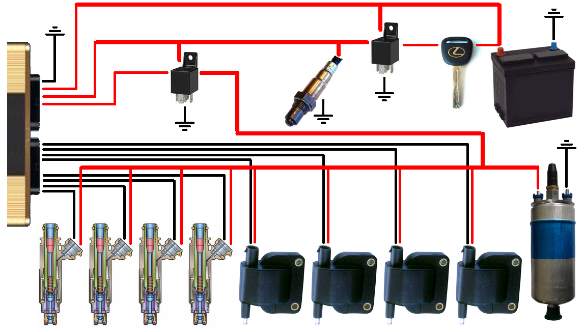
EMS Connections :
Fuses should be placed :
Can anyone see any problems with this approach? I sure hope not because the diagram looks quite good even if I do say so myself ;-)
Fred.
EDIT : See the next page instead of this : http://i260.photobucket.com/albums/ii15 ... wiring.png
EMS Connections :
- EMS ground
- Constant power to the EMS
- Ignition switched power to the EMS
- Fuel pump, injector and coil control line out of the EMS
- 4 (up to 12) coil control lines out of the EMS
- 4 (up to 12) injector control lines out of the EMS
- The ignition key switches the main relay which has constant power to it.
- The main relay feeds the wideband controller and heater, the switched EMS power, and the supply to the fuel pump, injector and coil control relay.
- The fuel pump, injector and control relay feeds all injectors, all coils and all fuel pumps.
Fuses should be placed :
- Between the battery and the ignition switch
- Between the battery and the main relay
- Between the battery and the constant power feed to the EMS
- Between the main relay and the wideband controller and heater
- Between the main relay and the fuel pump, injector and coil control relay
- Between the main relay and the switched power feed to the EMS
- Between the fuel pump, injector and coil control relay and the main injectors
- Between the fuel pump, injector and coil control relay and the staged injectors
- Between the fuel pump, injector and coil control relay and the coils
- Between the fuel pump, injector and coil control relay and the main fuel pump
- Between the fuel pump, injector and coil control relay and the lift pump
Can anyone see any problems with this approach? I sure hope not because the diagram looks quite good even if I do say so myself ;-)
Fred.
DIYEFI.org - where Open Source means Open Source, and Free means Freedom
FreeEMS.org - the open source engine management system
FreeEMS dev diary and its comments thread and my turbo truck!
n00bs, do NOT PM or email tech questions! Use the forum!
The ever growing list of FreeEMS success stories!
FreeEMS.org - the open source engine management system
FreeEMS dev diary and its comments thread and my turbo truck!
n00bs, do NOT PM or email tech questions! Use the forum!
The ever growing list of FreeEMS success stories!
-
gearhead
- LQFP112 - Up with the play
- Posts: 120
- Joined: Sun Feb 03, 2008 9:30 pm
- Location: Chicago, USA
Re: Power control of the EMS system
Looks great to me. You have convinced me. I say, "Run, Forrest, Run!"
Gearhead
Gearhead
Re: Power control of the EMS system
A few thoughts crossed my mind after posting, but all to do with wire size and paralleling of relays here and there etc.
I think it's quite elegant and should work very nicely.
OK, so PCB designers one and all, take note :
Fred.
I think it's quite elegant and should work very nicely.
OK, so PCB designers one and all, take note :
- 1 x relay control output (fuel pumps, injectors, coils)
- 1 x constant power input (for both "Wake up" and dirty power returns from injector diodes etc etc)
- 1 x switched power input (clean power supply for CPU)
- 2 x voltage regulators (by necessity now, one for CPU and one for sensors)
- 1 x constant battery feed for Vref independent of all this (such that current draw on the other lines does not affect the V reading)
Fred.
DIYEFI.org - where Open Source means Open Source, and Free means Freedom
FreeEMS.org - the open source engine management system
FreeEMS dev diary and its comments thread and my turbo truck!
n00bs, do NOT PM or email tech questions! Use the forum!
The ever growing list of FreeEMS success stories!
FreeEMS.org - the open source engine management system
FreeEMS dev diary and its comments thread and my turbo truck!
n00bs, do NOT PM or email tech questions! Use the forum!
The ever growing list of FreeEMS success stories!
Re: Power control of the EMS system
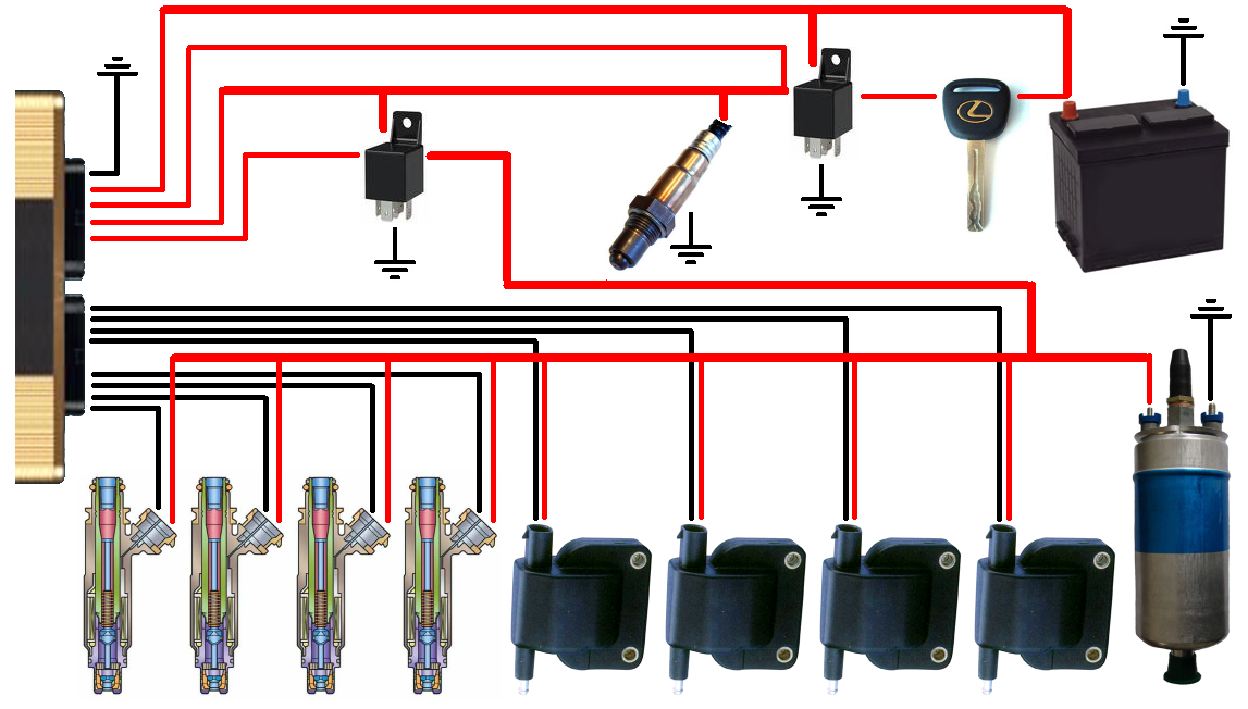
Take 2 :
EDIT : See next page instead of this : http://i260.photobucket.com/albums/ii15 ... iring2.png
Added the battery reference feed to the diagram.
EMS Connections :
Fred.
EDIT : See next page instead of this : http://i260.photobucket.com/albums/ii15 ... iring2.png
Added the battery reference feed to the diagram.
EMS Connections :
- EMS ground
- Constant power to the EMS
- Ignition switched battery Voltage reference to the EMS
- Ignition switched power to the EMS
- Fuel pump, injector and coil control line out of the EMS
- 4 (up to 12) coil control lines out of the EMS
- 4 (up to 12) injector control lines out of the EMS
Fred.
DIYEFI.org - where Open Source means Open Source, and Free means Freedom
FreeEMS.org - the open source engine management system
FreeEMS dev diary and its comments thread and my turbo truck!
n00bs, do NOT PM or email tech questions! Use the forum!
The ever growing list of FreeEMS success stories!
FreeEMS.org - the open source engine management system
FreeEMS dev diary and its comments thread and my turbo truck!
n00bs, do NOT PM or email tech questions! Use the forum!
The ever growing list of FreeEMS success stories!