jharvey wrote:I just released schematic A.05, perhaps you could comment on wire label names and the ignition driver schematic. I'm hoping to have these set's of schematics as rock solid as possible before I copy them making the multiple schematics I need to make the PCB.
I may be able to have a look later today. I'm already copping crap for taking too long to go out (on way out soon).
This version doesn't plan for O2, or other inputs. That is that the current game plan right? I'm trying to leave room for them, but not focusing on them right now.
O2 is just a generic ADC input as you have already designed. It's non essential, BUT, it should definitely be included in the design as it is just a pig to tune without one...
TPS, CHT, IAT, O2, MAP, atmos pressure, BatV, RPM x 2
The only one we can afford to drop is the atmos pressure if we have to, though it would be nice to have that.
My rugged block design :
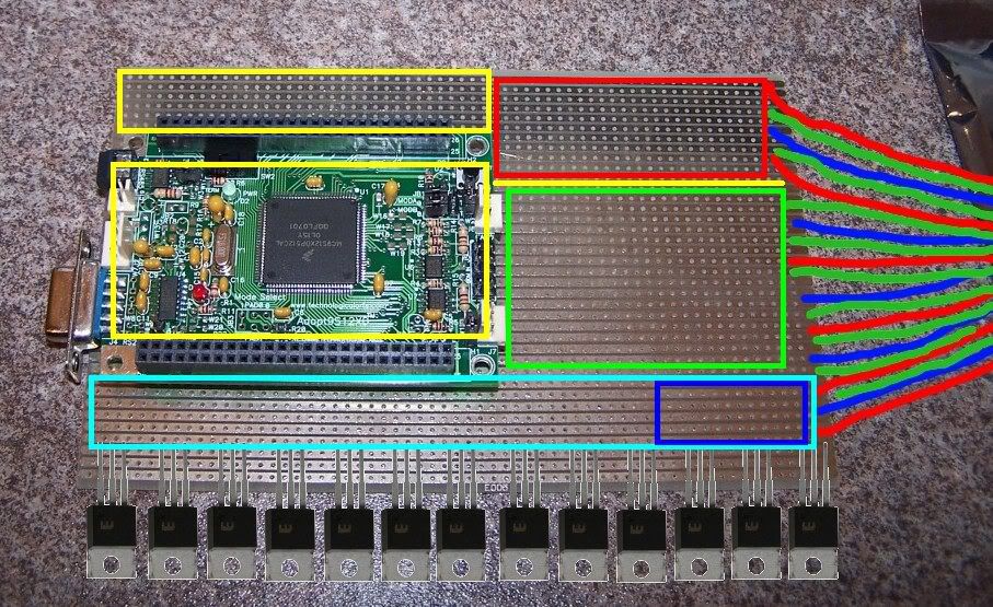
Yellow = ADC input conditioning and signal path
Red = RPM signal conditioning
Blue = power supply circuit
Pale blue = heavy traces and output conditioning stuff
Green = proto pads and also (I forgot) battery reference conditioning
Additionally I would REALLY like some 3mm LEDs paralleled with the output and RPM input circuits for a visual of proper operation, and perhaps some GPIO pins attached to LEDs on the front panel just to use as generic on car debugging in the short medium term.
The image is about 1:1 scale, but I have no idea how much room you need for everything. I do think putting power stuff close to connector/wiring is good though. I also think putting ADC stuff far away on the opposite side to the FETs/IGBTs/REGs is a good idea. Perhaps aim to put the TA board on the far side if that doesn't stuff you for routing from the second header. I think the RPM inputs should be conditioned close to the IO wiring too.
The four corners of the TA board should be supportable by screws/standoffs, so include those.
Based on my VERY rough diagram I make it 13 to220 packs. 2 regulators cuts it to 11, 1 cuts it to 12,
4 injectors or 6 injectors
1 fuel pump FET
1 regulator or 2 regulators
Leaves 3 - 6 spare FETs/IGBTs
How about :
4 Injector FETs
4 Ignition IGBTs
2 Regulators (both 5v)
1 Fuel pump FET
2 Spare FETs
That way as a stand alone unit it can run a 4 cylinder properly with 2 spare outputs and a solid power setup.
On second thoughts considering how easy it is to add more boards to a TA based setup, scratch the proto area and use that space to make the rest of the basic features more complete and robust. You might need the space anyway.
Lastly, you may not be able to get 13 to220 on there. If not, 11 is enough to do what needs to be done.
Gasp :-)
Fred.


