
Lets add this to the list fairchild ISL9V2540S3ST and FGB3040CS
The FGB3040CS has current sensing capabilities, however the ISL9V2540S3ST offers a more standard package allowing for alternate sourcing. Perhaps pads can be placed for both chips? Is there a preference for one or the other, or a preference for a different chip altogether?
Ignition IGBT
Re: Ignition IGBT
So this driver you've talked about Fred, what's it look like kind of. Is there a chip you recommend? Perhaps it has a reference schematic.

Re: Ignition IGBT
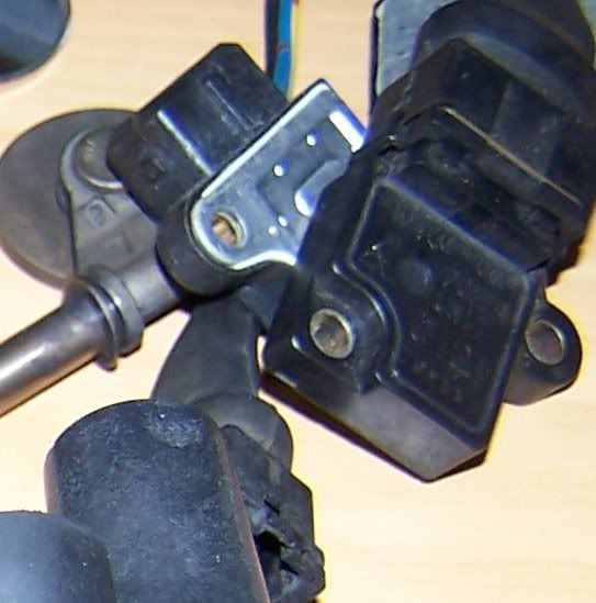
Do you mean that ^ ?Fred wrote:I personally prefer OEM ignitors. It's really hard to beat their physical packaging and robustness and they are electrically tolerant as well. I used J121 and equivalent units as have a few of my mates, but most of them are fairly good.
If so :
Fred.
DIYEFI.org - where Open Source means Open Source, and Free means Freedom
FreeEMS.org - the open source engine management system
FreeEMS dev diary and its comments thread and my turbo truck!
n00bs, do NOT PM or email tech questions! Use the forum!
The ever growing list of FreeEMS success stories!
FreeEMS.org - the open source engine management system
FreeEMS dev diary and its comments thread and my turbo truck!
n00bs, do NOT PM or email tech questions! Use the forum!
The ever growing list of FreeEMS success stories!
-
GrowlingandBiffo
- QFP80 - Contributor
- Posts: 56
- Joined: Sat Apr 26, 2008 7:42 am
Re: Ignition IGBT
The Ford EDIS is very robust, and consequently the V2.2 and V2.5 that utilise it never seem to have any reliability issues, unlike the V3...
The grass track racers prefer EDIS, in this application, as they say gives better power (not more) and is reliable, cheap and plentiful.
Aston-Martin used the EDIS 8 on the twin Super Charged V8 and this was before Henry bought the company.
The grass track racers prefer EDIS, in this application, as they say gives better power (not more) and is reliable, cheap and plentiful.
Aston-Martin used the EDIS 8 on the twin Super Charged V8 and this was before Henry bought the company.
Re: Ignition IGBT
Unfortunately EDIS is not an ignitor and removes your ability to do quite a few things. I'll not be writing support code for EDIS for a long long time if ever. EDIS was a hack coded to do decent ignition when MS didn't support any. EDIS has rock solid timing accuracy UNLIKE MS1 hence the "better power" comments probably. Better than poor/average doesn't make it a non hack to use though.
Fred.
Fred.
DIYEFI.org - where Open Source means Open Source, and Free means Freedom
FreeEMS.org - the open source engine management system
FreeEMS dev diary and its comments thread and my turbo truck!
n00bs, do NOT PM or email tech questions! Use the forum!
The ever growing list of FreeEMS success stories!
FreeEMS.org - the open source engine management system
FreeEMS dev diary and its comments thread and my turbo truck!
n00bs, do NOT PM or email tech questions! Use the forum!
The ever growing list of FreeEMS success stories!
Re: Ignition IGBT
Still looking for a recommendation here. It's the last foot print I have to decide on before I start with the PCB layout. I don't really need a vendor part number, but it helps allot. Lets me know pin 1, footprint ect.Fred wrote:Do you mean that ^ ?Fred wrote:I personally prefer OEM ignitors. It's really hard to beat their physical packaging and robustness and they are electrically tolerant as well. I used J121 and equivalent units as have a few of my mates, but most of them are fairly good.
Does the schematic look good? I seem to recall these MOSFET's were buffering for a larger FET or IGBT.
Re: Ignition IGBT
You may have missed it, but in the other thread we all decided that we would include IGBTs on the board and that we would also included tri state buffers and/or XOR chips to allow hardware inversion of the output. Another option is some sort of buffer that can be had in inverting and non inverting types. I suspect configurability is a better choice though.
When I was saying "use little fets to buffer" I wasn't aware that there were readily available ICs that could do a good job of buffering lots of channels. Now that I am I favour that approach.
As for which IGBT, I think most are pin compatible. The BIP373 that DIYautotune sells is not available anywhere else, but is all protected. The others are more grunty, but not protected. Several members on here have had good luck with different ones, we should just compare pinouts and choose one for it's footprint only.
Fred.
DIYEFI.org - where Open Source means Open Source, and Free means Freedom
FreeEMS.org - the open source engine management system
FreeEMS dev diary and its comments thread and my turbo truck!
n00bs, do NOT PM or email tech questions! Use the forum!
The ever growing list of FreeEMS success stories!
FreeEMS.org - the open source engine management system
FreeEMS dev diary and its comments thread and my turbo truck!
n00bs, do NOT PM or email tech questions! Use the forum!
The ever growing list of FreeEMS success stories!
Re: Ignition IGBT
I seem to recall davebmw noted ignition current sensing, but I can't seem to find it now, so I'll bring it up here. I seem to recall it used a zener and a resistor, perhaps another part or two. Dave (or who ever posted it), can you elaborate? I'd like to make sure I have included provisions to add it to the additional modules, if not added now.
With the vision of add-on modules, the ignition current sense feature will likely need to be added to the plan now. I believe it will need to be in-line, somewhere, I'm not sure if it works on the low power primary drivers we have, or if it sits right next to the coil and sends the signal back.
If it needs to be in-line with what we have, I see two ways it can happen. We can draft a schematic of it now, then we can either add it now, or we can add a couple via's, that will allow for this feature in the future via add-on card. Of course these features will be jumpered out by default.
-
davebmw
- LQFP144 - On Top Of The Game
- Posts: 331
- Joined: Sun Jul 13, 2008 2:58 pm
- Location: South Wales, UK
Re: Ignition IGBT
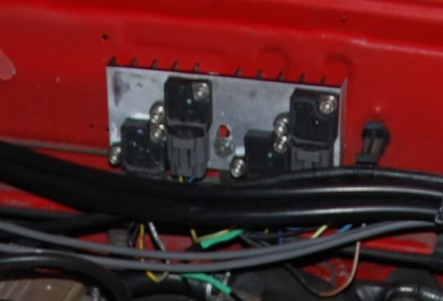
The BMW system is essentially a 240R resistor on the low side of the HT windings of the Coil packs one side of which is tied to ground the other has a screened sense wire back to the ECU.
when you have a sucessful spark event the voltage measured across the resistor is relative to the current flowing in the HT side of the ignition circuit.
As Fred rightly pointed out that is and OEM feature to enable the next generation of lazy grease monkeys to sell you coil packs at your next service. It probably has little benefit in FreeEMS 1.0 or 2.0.
This is right up there with (or getting close to) ion sensing and other overly complex trickery such as quantum physics, super hadron collider theory and understanding female shopping habits!
For future development however it could develop into a dash mounted indicator that says in big red letters "Clean your Spark Plugs Dumbass!"
93'BMW 325is M50B25TU, Rebuilt 06/06, JE10.5:1, polish&port. Scorpion BB, K&N CAI, TEJ21 WBO2, '07 M3 Evo 18" 225F, 255R, EBC Kevlar, Bilstien Sprint, Polyflex. Head rebuild Oct'08, OEM+FSE FPR, MS2v3.0_DJB Custom, Extra 2.0.1
Re: Ignition IGBT
I like the spark plug cleaning note. So it's not in the primary windings correct? It's in the secondary. Then it functions as either an analog return, or a digital return. So it also doesn't need to be inserted in the low side driver, and room for it does not need to be maintained on the board.
It could easily be added after the fact, on an addon card, that has access to the analog, or digital inputs.
Does that sound right?
It could easily be added after the fact, on an addon card, that has access to the analog, or digital inputs.
Does that sound right?