Is it OK to use one vnp10n07 to drive four high-Z injectors?

From DIY contraptions to sophisticated FreeEMS-specific designs! Plus general hardware development!
User avatar
HotCat
LQFP112 - Up with the play
Posts: 110
Joined: Wed Apr 13, 2011 2:35 am

Re: Is it OK to use one vnp10n07 to drive four high-Z inject

Post by HotCat »

1 Fuel Pump relay drive. PA7
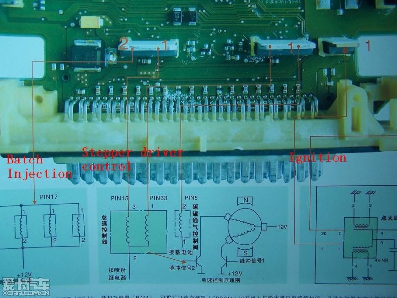
1 dash board tacheometer drive. PP5
1 pair of idle air valve drive. PP6&PP7
1 gas tank ventilation valve drive. PP3
Fred wrote: CPU, analogue should be one ground, but it comes in from the head/block/battery for the CPU and then goes out to the sensors from the ECU. ignition drive should share CPU ground IF it's low current. If it's high current, it should be isolated. Injector and low side ground(s) should be isolated.

What do you need an O2 sensor ground for? That worries me. That should typically have its own controller which grounds independently and just shares a signal line. Heater grounds for built in O2 stuff should be isolated.

Fred.
I draw a diagram represent my GND design
6.JPG
User avatar
Fred
Moderator
Posts: 15431
Joined: Tue Jan 15, 2008 2:31 pm
Location: Home sweet home!
Contact:

Re: Is it OK to use one vnp10n07 to drive four high-Z inject

Post by Fred »

Relay is correct
Tacho could go on a more boring pin, but will work fine there, and gives you more options there.
Gas tank ventilation is good where it is IF it's a PWM valve, if not, you could put it on any other boring pin (like A or B) if you're not using PWM pins for anything else, though, then it's no waste.

How does your idle valve work? Is it 3 wire? Like toyota and bmw? Why do you need two drivers for it? Tell me more and maybe I can advise.

The grounding is very wrong, like MS grounding, which causes a lot of trouble.

You CAN ground your LC-1 like that, no problem, but you don't need to. It should have a ground shared with the block, just like the ECU and LC1 heater.

You can't have a looped star system. You can have more than one star.

The ground for the low side drivers especially the injectors should be a totally separate circuit and wire all the way back to the block.

The sensor ground is good.

The ignition ground.... do you have ignitors? Or are you driving your coils directly from IGBTs or darlingtons inside the case?

I suspect that you have ignitors and that ignition ground is CPU/reference ground. Am I right? If so, the only thing you need to do is split the low side ground off from the rest of the grounds and treat it like it was in another box. If you're worried about the voltage sag causing in effective switching of them, then run an ADC channel to the low side ground so you can monitor it in logs, like RavAGE.

If that doesn't make sense, please ask again :-)

Fred.
DIYEFI.org - where Open Source means Open Source, and Free means Freedom
FreeEMS.org - the open source engine management system
FreeEMS dev diary and its comments thread and my turbo truck!
n00bs, do NOT PM or email tech questions! Use the forum!
The ever growing list of FreeEMS success stories!
User avatar
HotCat
LQFP112 - Up with the play
Posts: 110
Joined: Wed Apr 13, 2011 2:35 am

Re: Is it OK to use one vnp10n07 to drive four high-Z inject

Post by HotCat »

my idle valve has 3 wire, two coil build in. One coil pull the valve toward the open side and the other coil pull the valve toward close side. So given two different duty cycle of PWM signal applied to the two coil make the valve station at some position. So I should have two PWM ports to control it and this is what the OEM do.

for LC1 connection, I should follow your advise and reuse OEM narrow band O2 harness

I copy the looped star system from my OEM ECU, in Bosch's design, injector drive gnd, low side gnd, on board ignition drive gnd, sensor gnd, sensor wire shield gnd, CPU gnd were internally connected together forming a start connection. Center of the start was the voltage regulator

I previously made a assumption that OEM design was always correct and it runs my engine for a decade without failure. If doing so is very wrong, I should follow your suggestion and separate the injector gnd, on board igniter gnd. Made them only connect the OEM pins which lead all the way to the engine block.

and is it necessary to separate the injector gnd from low side gnd? According to my study on OEM harness, the ECU only fan out 2 pins that connect to the block directly
User avatar
Fred
Moderator
Posts: 15431
Joined: Tue Jan 15, 2008 2:31 pm
Location: Home sweet home!
Contact:

Re: Is it OK to use one vnp10n07 to drive four high-Z inject

Post by Fred »

If you only have two pins connecting to the block independently, use one for cpu ground and the other for high current low side ground. You can make a provision to join them together later if you wish.

The OEM made a choice. They realised that the impact on sensor readings only extends to the battery voltage and that you can filter that in hw and software enough to not matter. I prefer a more accurate approach of not allowing the low side currents to disrupt the reference ground and cause the 12v signal to appear different to reality.

You may go which ever way you choose, however if you go with star inside ecu and high current shared with reference, don't complain to me when you've got noise on your signals.

One ground for injectors, idle, etc is fine. No need to split them off, really.

having the remaining stuff star at the Vreg is ideal, though, so keep that aspect.

Re the 3 wire valve, that's the same as BMW and toyota. The plan of attack there, and what the BMW ECU does, and likely the toyota too, and the Ravage schems is to use one high resolution PWM and an inverter IC such that it works like this: 50/50 30/70 10/90 etc. If you want to run it with two independent signals and write code to handle that scenario, that's cool, I guess. Custom code will always be cool, but it won't always be integrated. Are you certain that two cpu pins control those two outputs? and not some logic like bmw (also bosch) and ravage are doing?

Fred.
DIYEFI.org - where Open Source means Open Source, and Free means Freedom
FreeEMS.org - the open source engine management system
FreeEMS dev diary and its comments thread and my turbo truck!
n00bs, do NOT PM or email tech questions! Use the forum!
The ever growing list of FreeEMS success stories!
lumpensack2003
QFP80 - Contributor
Posts: 38
Joined: Sun Oct 26, 2008 11:32 pm

Re: Is it OK to use one vnp10n07 to drive four high-Z inject

Post by lumpensack2003 »

Hi HotCat,

keep on going - great effort so far!

I think it's not a good idea to alter the pin assignment of the BDM connector.
Keep in mind that this assignment is around for years and lots of programmers and ICEs come in stock with a matching connector.
Nevertheless I follow your concern about wrong plugging.
Some years ago I made up a new symbol and package for the BDM connector in EAGLE (with is my favourite eCAD tool). It's the normal 2-row, 6-pin pinhead connector - but the 2 unused pins don't have a hole / pad / via.
Now you can plug the 2 unused holes in the programmer's connector with some hotglue and are done. Good thing is that you remain compatibility with programmers that don't have this 2 holes plugged.

Cheers,
GJ
scirturbo
TO92 - Vaguely active
Posts: 2
Joined: Thu Oct 30, 2008 8:25 pm
Location: Netherlands

Re: Is it OK to use one vnp10n07 to drive four high-Z inject

Post by scirturbo »

See tech articles. A bit outdated but informative....

http://www.autoshop101.com/

Simon
User avatar
HotCat
LQFP112 - Up with the play
Posts: 110
Joined: Wed Apr 13, 2011 2:35 am

Re: Is it OK to use one vnp10n07 to drive four high-Z inject

Post by HotCat »

Fred wrote:If you only have two pins connecting to the block independently, use one for cpu ground and the other for high current low side ground. You can make a provision to join them together later if you wish.
Today, I comfired that three pins connecting to the block independently. So I have one ignition gnd, one low side gnd as well as CPU gnd.
You may go which ever way you choose, however if you go with star inside ecu and high current shared with reference, don't complain to me when you've got noise on your signals.
I'll go the right way and won't let your down
One ground for injectors, idle, etc is fine. No need to split them off, really.
Yes, one dedicated gnd for injectors and all low sides
Are you certain that two cpu pins control those two outputs? and not some logic like bmw (also bosch) and ravage are doing?
Fred.
I am pretty sure about that, here is a diagram
Image
User avatar
HotCat
LQFP112 - Up with the play
Posts: 110
Joined: Wed Apr 13, 2011 2:35 am

Re: Is it OK to use one vnp10n07 to drive four high-Z inject

Post by HotCat »

lumpensack2003 wrote: I think it's not a good idea to alter the pin assignment of the BDM connector.
Keep in mind that this assignment is around for years and lots of programmers and ICEs come in stock with a matching connector.
My BDM pod require such pin assignment, doing so will prevent CPU damage when connect BDM in reverse polarity condition. You checkout my git repo and see my progress at github.com/HotCat/FireCat
User avatar
HotCat
LQFP112 - Up with the play
Posts: 110
Joined: Wed Apr 13, 2011 2:35 am

Re: Is it OK to use one vnp10n07 to drive four high-Z inject

Post by HotCat »

scirturbo wrote:See tech articles. A bit outdated but informative....

http://www.autoshop101.com/

Simon
Nice found, I like it
User avatar
Fred
Moderator
Posts: 15431
Joined: Tue Jan 15, 2008 2:31 pm
Location: Home sweet home!
Contact:

Re: Is it OK to use one vnp10n07 to drive four high-Z inject

Post by Fred »

When you say "ignition ground" what sort of ignition system do you have? Is it distributor or wasted spark or what? Does the OEM ECU drive the coil directly (terrible idea) or through an ignitor? If it drives the coil directly, then you need to either share grounds with the other low side stuff or have one for ign, one for other low side, and one for CPU. I'm going to assume that it uses an ignitor, though:

"Yes, one dedicated gnd for injectors and all low sides" Perfect, now you just need to decide if you use two pins for that or only one and use two for the reference ground. Likely you'll want to use two pins for the high current stuff and just make sure the other one is in good condition. Make sense?

Ahhhh, stepper! OK, you actually need a stepper controller chip connected to those pins, a lot like Marcos did in Puma. You could try to drive a stepper directly, but it's much better not to. I was going to say google, but let me find you a link or two.

http://www.omega.com/prodinfo/stepper_motors.html
http://www.divms.uiowa.edu/~jones/step/
http://www.freescale.com/files/microcon ... AN2974.pdf
http://en.wikipedia.org/wiki/Stepper_motor
http://www.sparkfun.com/products/10267

There is no code for this, but it shouldn't be too hard to write it.

Fred.
DIYEFI.org - where Open Source means Open Source, and Free means Freedom
FreeEMS.org - the open source engine management system
FreeEMS dev diary and its comments thread and my turbo truck!
n00bs, do NOT PM or email tech questions! Use the forum!
The ever growing list of FreeEMS success stories!
Post Reply