
If someone wants to pickup the task of creating an adapter card to a adapt the adapt card (say that 3 times fast!) to the DIP40 MegaSquirt format such that the code can be more easily tested by those with existing hardware, that would be cool.
The best way I can see for it is a small daughter card to hold the adapt card, and another small card with a 40 pin header on it that plugs into the DIP40 socket on a v2.2/v3.0/v3.57 board and allows the use of the std megasquirt input conditioning for our core. The two small cards could be connected with a short old non ATA IDE cable and you are instantly in business. You will also need to add extra ignition and injection outputs via another board and cable, but that should be pretty easy.
The IDE cable idea has noise draw backs obviously, and a plug in card would be a better choice. Discuss your ideas here and we'll see what happens :-)
Making the pins jumperable is advisable such that I can change my mind about which function lives where without it ruining your design.
If someone comes up with such a thing, "only" the code is left to add in for real testing to begin.
This is a pretty easy task for any reasonable hardware guy I would think.
I have no ms main board myself, so I don't need one of these, but most everyone else probably does, and could just use what they have already with such a board. This could make testing much easier and more attractive to a wider group of people.
Of course, they will still need code for their particular trigger type, but that will come with time for sure.
Admin.
MegaSquirt main board adapter card design
MegaSquirt main board adapter card design
DIYEFI.org - where Open Source means Open Source, and Free means Freedom
FreeEMS.org - the open source engine management system
FreeEMS dev diary and its comments thread and my turbo truck!
n00bs, do NOT PM or email tech questions! Use the forum!
The ever growing list of FreeEMS success stories!
FreeEMS.org - the open source engine management system
FreeEMS dev diary and its comments thread and my turbo truck!
n00bs, do NOT PM or email tech questions! Use the forum!
The ever growing list of FreeEMS success stories!

Re: MegaSquirt main board adapter card design
holy crap mate, that's an awesome idea! How did i not think of that??? 
Legal disclaimer for all my posts: I'm not responsible for anything, you are responsible for everything. This is an open and free world with no strings attached.
Re: MegaSquirt main board adapter card design
Considering that that is all that MS2 actually is, I'm not sure :-)
Think of it as MS3 by a different name until MS3 becomes reality whenever that occurs :-)
Think of it as MS3 by a different name until MS3 becomes reality whenever that occurs :-)
DIYEFI.org - where Open Source means Open Source, and Free means Freedom
FreeEMS.org - the open source engine management system
FreeEMS dev diary and its comments thread and my turbo truck!
n00bs, do NOT PM or email tech questions! Use the forum!
The ever growing list of FreeEMS success stories!
FreeEMS.org - the open source engine management system
FreeEMS dev diary and its comments thread and my turbo truck!
n00bs, do NOT PM or email tech questions! Use the forum!
The ever growing list of FreeEMS success stories!
Re: MegaSquirt main board adapter card design
Excellent idea! I'll see what I can do 
Re: MegaSquirt main board adapter card design
That's the (DIY enginuitive) spirit! :-)
DIYEFI.org - where Open Source means Open Source, and Free means Freedom
FreeEMS.org - the open source engine management system
FreeEMS dev diary and its comments thread and my turbo truck!
n00bs, do NOT PM or email tech questions! Use the forum!
The ever growing list of FreeEMS success stories!
FreeEMS.org - the open source engine management system
FreeEMS dev diary and its comments thread and my turbo truck!
n00bs, do NOT PM or email tech questions! Use the forum!
The ever growing list of FreeEMS success stories!
Re: MegaSquirt main board adapter card design
Ok, i think i'll go ahead and take upon myself the administrative/project management/design(high level) part of this effort.
Let me summarize the goal/purpose:
"To have a solution for attaching/connecting (one header side) of the XDP Adapt board that we're using to the 40DIP socket on the V3 board."
I'll start with requirements: (feel free to add yours)
- Has to be sturdy/robust and vibration/shock resilient
- Possibly fit into the MS standard case
- Have appropriate hardware re-configuration devices, for fast and clean reconfiguring if needed. (use micro dip switches?)
- Contain any kind of signal conversion/buffering/protection needed to connect straight to the Adapt board header
Legal disclaimer for all my posts: I'm not responsible for anything, you are responsible for everything. This is an open and free world with no strings attached.
Re: MegaSquirt main board adapter card design
Thanks for initiating discussion on the finer points of it.ababkin wrote:Ok, i think i'll go ahead and take upon myself the administrative/project management/design(high level) part of this effort.
Fixed it for ya :-)Let me summarize the goal/purpose:
"To have a solution for attaching/connecting (BOTH header sides because the pins that we need to use are distributed between them both) of the XDP Adapt board that we're using to the 40DIP socket on the V3 board and an additional board containing sequential ign/injection drivers etc."
We should keep it in mind that this is a VERY temporary effort to ease transition for users willing to test on their vehicles. Thus no excess effort should be put into it that could be better used elsewhere.I'll start with requirements: (feel free to add yours)
- Has to be sturdy/robust and vibration/shock resilient AGREED
- Possibly fit into the MS standard case AGREED
- Have appropriate hardware re-configuration devices, for fast and clean reconfiguring if needed. (use micro dip switches?) (ONLY IN SOME PLACES)
- Contain any kind of signal conversion/buffering/protection needed to connect straight to the Adapt board header (There shouldn't be much required, but OK.)
My proposal (as discussed offline with Karri who is designing it as we type) is :
small as possible physical board with DIP40 and Adapt footprint on it. This way the board can be plugged in in place of the processor and the adapt board plugged into it. Extra mounting can come from standoffs or spacers or something that just stop it from moving by being in the way. There isn't much you could really attach it to inside the case. I'm unsure how large it can be without fowling components on a typical board as installed in my car or yours. If there isn't enough real estate available, then we may need to move it up or put it on a ribbon + 2 cores of power/ground.
My strong preference would be to avoid ribbon for the main connection.
My preference for the cable to the extra board is a 40 pin ribbon as they are cheap and easy to get.
Alternatively I guess we could lay out the board to contain the drivers etc on it and run heavier cables straight out of the case as in the style of the extra DB15 that 3.57 and extra mods recommend.
Was going to post up a pic of that board that takes a spare core : "bandwidth exceeded"
Next time...
Admin.
DIYEFI.org - where Open Source means Open Source, and Free means Freedom
FreeEMS.org - the open source engine management system
FreeEMS dev diary and its comments thread and my turbo truck!
n00bs, do NOT PM or email tech questions! Use the forum!
The ever growing list of FreeEMS success stories!
FreeEMS.org - the open source engine management system
FreeEMS dev diary and its comments thread and my turbo truck!
n00bs, do NOT PM or email tech questions! Use the forum!
The ever growing list of FreeEMS success stories!
Re: MegaSquirt main board adapter card design
Good idea on making it ribbon-less.
i wonder if we can just get tall sockets for the Adapt headers. If we do that, there'll hopefully be enough space for some components underneath the Adapt. But then there may be issues with fitting Adapt + adapter board into the original case. We need to do some measuring. Or even try to lower the v3 board and cut new endplates (and provide for extra connectors, etc).
Glen once told me that he was gonna make a taller case to comfortably fit v3 board together with the Extra daughter-board (by Error). Taller + extra DB25 would be great for this
EDIT: also i don't agree with the "small as possible" requirement. We need to maximize (or at least make it ample enough) the usable space on it (i.e the space that is not underneath the Adapt board) to fit various components on it. The board shape needs to be determined while considering clearance with the V3 and the case itself.
Alex
Legal disclaimer for all my posts: I'm not responsible for anything, you are responsible for everything. This is an open and free world with no strings attached.
Re: MegaSquirt main board adapter card design
There just isn't anything much that needs to be on the board except the CPU card and 40 pin headers. Keeping it minimal = reducing entry cost/difficulty. Once we have basic fuel/ign up and running using the same sensors as MS does (automotive industry standard stuff) then people will be making up real board designs of our own and starting to test them on their cars as they will eventually run. This is a stop gap and nothing more, as such it should be reasonably well though through and fairly minimal. the 40 pin IDE cable can carry away the signals that are extra over and above what you normally use. (sequential injectors and ignition etc). Hence small cheap easy fast = make it actually happen sooner and people actually attempt to use them.
Admin.
Admin.
DIYEFI.org - where Open Source means Open Source, and Free means Freedom
FreeEMS.org - the open source engine management system
FreeEMS dev diary and its comments thread and my turbo truck!
n00bs, do NOT PM or email tech questions! Use the forum!
The ever growing list of FreeEMS success stories!
FreeEMS.org - the open source engine management system
FreeEMS dev diary and its comments thread and my turbo truck!
n00bs, do NOT PM or email tech questions! Use the forum!
The ever growing list of FreeEMS success stories!
Re: MegaSquirt main board adapter card design
http://www.glensgarage.com/catalog/msex ... -p-89.html
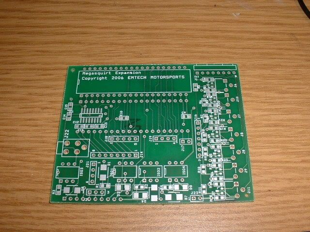
Looks like we'll be OK :-)
Do any of our users have one of these installed that they can photograph?
Admin.
Looks like we'll be OK :-)
Do any of our users have one of these installed that they can photograph?
Admin.
DIYEFI.org - where Open Source means Open Source, and Free means Freedom
FreeEMS.org - the open source engine management system
FreeEMS dev diary and its comments thread and my turbo truck!
n00bs, do NOT PM or email tech questions! Use the forum!
The ever growing list of FreeEMS success stories!
FreeEMS.org - the open source engine management system
FreeEMS dev diary and its comments thread and my turbo truck!
n00bs, do NOT PM or email tech questions! Use the forum!
The ever growing list of FreeEMS success stories!