
That's a good idea!
The extra IO is required though as sequential/semi sequential is a big part of the reason for this whole thing. Having a small header for the ign and inj channels is a non issue though.
I guess you could get it down to around the 40US mark and with less physical connections too. It would only be worth it for those with an existing installation though. For anyone else a full new board would be a better plan. (same goes for the adapter idea)
Fred.
MegaSquirt main board adapter card design
Re: MegaSquirt main board adapter card design
DIYEFI.org - where Open Source means Open Source, and Free means Freedom
FreeEMS.org - the open source engine management system
FreeEMS dev diary and its comments thread and my turbo truck!
n00bs, do NOT PM or email tech questions! Use the forum!
The ever growing list of FreeEMS success stories!
FreeEMS.org - the open source engine management system
FreeEMS dev diary and its comments thread and my turbo truck!
n00bs, do NOT PM or email tech questions! Use the forum!
The ever growing list of FreeEMS success stories!
Re: MegaSquirt main board adapter card design
They stole our idea!!! I say we sue! (joking...)
Fred.
DIYEFI.org - where Open Source means Open Source, and Free means Freedom
FreeEMS.org - the open source engine management system
FreeEMS dev diary and its comments thread and my turbo truck!
n00bs, do NOT PM or email tech questions! Use the forum!
The ever growing list of FreeEMS success stories!
FreeEMS.org - the open source engine management system
FreeEMS dev diary and its comments thread and my turbo truck!
n00bs, do NOT PM or email tech questions! Use the forum!
The ever growing list of FreeEMS success stories!

Re: MegaSquirt main board adapter card design
He he. Stole the open design.
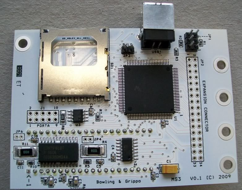
Some things I find interesting about that board. They often have a path that allows for a very large trace, yet it appears they used about a 5mil trace. If they used larger traces, they could have used something other than 2oz copper, freeing up the production abilities. I also see they simply ignored soldering some pads and a thru hole. I'm sure this is because those pins aren't used, and they apparently don't care about mechanical stability. However, even when prototyping, it takes more time to not solder them, then it does to simply solder them. Unless they are using a crappy proto process that is. Also also, not the ones that are soldered are also bad. See how many have sunk down in a v or look like a water drop sitting on a surface. Both bad mechanical design, looking for cracks to happen, and cause intermittent problems both with inconsistent resistive components as well as inconsistent capacitive components. Also the vias should have larger thermals, these ones barely allow the hole to fit, production runs will likely have failed or partly failed vias. Also, also, also, they didn't flood the unused space with copper, and certainly didn't ground the flooded area. This make for bad RF design. Your asking for coupling of components from the below board, near by components, ect. I wouldn't proto with this board.
Feels like I should plug the software dev. Would be nice if we can get this out before MS3.
Re: MegaSquirt main board adapter card design
It's funny you should say that!jharvey wrote:Feels like I should plug the software dev. Would be nice if we can get this out before MS3.
http://www.diyefi.org/forum/viewtopic.p ... 8068#p8068
It would be nice to have a runner about the time they release their board for sale.
Fred.
DIYEFI.org - where Open Source means Open Source, and Free means Freedom
FreeEMS.org - the open source engine management system
FreeEMS dev diary and its comments thread and my turbo truck!
n00bs, do NOT PM or email tech questions! Use the forum!
The ever growing list of FreeEMS success stories!
FreeEMS.org - the open source engine management system
FreeEMS dev diary and its comments thread and my turbo truck!
n00bs, do NOT PM or email tech questions! Use the forum!
The ever growing list of FreeEMS success stories!
-
longracing

- LQFP112 - Up with the play
- Posts: 140
- Joined: Wed Jul 16, 2008 9:21 am
- Location: NSW, Australia
Re: MegaSquirt main board adapter card design
It's good to see they have something working. SD, USB and expansion connections are great but it does feel a bit like a band-aid solution rather than a new exciting product.
Wouldn't it take up less space and be able to fit everything on one board with everything SMT (except the mosfets, for heatsink mounting)? Or even have a new signal processing board with the drivers/mosfets on a seperate board, a seperate board with room for more than 2 x fuel and 1 x ignition driver. If it was two boards then there would be enough room for thru-hole components, I assume they want to keep thru-hole components for the DIY kits.
Wouldn't it take up less space and be able to fit everything on one board with everything SMT (except the mosfets, for heatsink mounting)? Or even have a new signal processing board with the drivers/mosfets on a seperate board, a seperate board with room for more than 2 x fuel and 1 x ignition driver. If it was two boards then there would be enough room for thru-hole components, I assume they want to keep thru-hole components for the DIY kits.
-
TurboVocho
- TO92 - Vaguely active
- Posts: 1
- Joined: Thu Feb 25, 2010 11:59 pm
Re: MegaSquirt main board adapter card design
Hi
i want to help build an adapter card to test FreeEms in my pcb v3 instaled in 1993 mexican bug
best regards
i want to help build an adapter card to test FreeEms in my pcb v3 instaled in 1993 mexican bug
best regards
Re: MegaSquirt main board adapter card design
How's this project going? Turns out I have a v3.57 MS board that has not been completed, and I've got a Adapt on order. This might actually be a good path for me, I can get my bike running with the MS-II I have so I have a known good platform and then be able to easily transition to the better.
Although, I'd have to use a DB-37. Ugh. What a stupid connector for a ECU.
Although, I'd have to use a DB-37. Ugh. What a stupid connector for a ECU.
Re: MegaSquirt main board adapter card design
AFAIK no one is working on it.
DIYEFI.org - where Open Source means Open Source, and Free means Freedom
FreeEMS.org - the open source engine management system
FreeEMS dev diary and its comments thread and my turbo truck!
n00bs, do NOT PM or email tech questions! Use the forum!
The ever growing list of FreeEMS success stories!
FreeEMS.org - the open source engine management system
FreeEMS dev diary and its comments thread and my turbo truck!
n00bs, do NOT PM or email tech questions! Use the forum!
The ever growing list of FreeEMS success stories!
Re: MegaSquirt main board adapter card design
Well, it sounds useful to me. Do you have a MS main board?
I'm not sure how well stacking the boards will work, the Adapt board's weight plus an adapter board will probably be too much, unless you use some standoffs to locate the MS mounting holes. I'll stare at it some more, but you can put me down for working on this, as I see it as a good step.
I'm not sure how well stacking the boards will work, the Adapt board's weight plus an adapter board will probably be too much, unless you use some standoffs to locate the MS mounting holes. I'll stare at it some more, but you can put me down for working on this, as I see it as a good step.
Re: MegaSquirt main board adapter card design
OK, awesome! Yeah, you'd need the stand-off idea if it was going to see any significant road time, that's for sure. I do indeed have a MS board, a v3.0 with medium mods to do COP and make the noise issues less severe, but not gone. If we did the adapter, we'd probably want to adapt all the other stuff, but NOT the fuel/ign pins, and put them out on another header or similar, much as they do with MS3 :-)
Fred.
Fred.
DIYEFI.org - where Open Source means Open Source, and Free means Freedom
FreeEMS.org - the open source engine management system
FreeEMS dev diary and its comments thread and my turbo truck!
n00bs, do NOT PM or email tech questions! Use the forum!
The ever growing list of FreeEMS success stories!
FreeEMS.org - the open source engine management system
FreeEMS dev diary and its comments thread and my turbo truck!
n00bs, do NOT PM or email tech questions! Use the forum!
The ever growing list of FreeEMS success stories!