My thought is that resistors should be 1/8 watt through hole (a bit smaller) and all we really need unless I am missing something. Caps, also through hole.
The only SMD I am for are the omnifets, really. They are cheaper, smaller and more easily available over here. I can live with to220 or even to262/ipak (same as a dpak, but with longer leads for through hole mounting, they are just not available as far as I can tell, though). I am running a vnd5n07 in ipak format as my PWM driver for my IAC. It is not connected to any heat sink and does not get even warm.
As for fully protected fets that are to92, I do not know of any.
KeithG
PCB layout - JHarvey

Re: PCB layout
I've heard preferences for thru hole, vs smd, but I haven't seen it backed by more then feeling. I personally don't like thru hole because it means every part requires a via, so the home brew guy has a lot of drilling. SMD removes the requirement of the via, so less drilling, and less torn up traces because your drill weld dull.
Are there reasons why you prefer thru hole, or is it simply what your familiar with?
Are there reasons why you prefer thru hole, or is it simply what your familiar with?
Re: PCB layout
My current game plan is for both DPAK and TO220 foot prints. I'll find out how well that plays along when I start the PCB layout.
Hmmm, Perhaps I can do the same with the resistors and other discretes..... However that's a lot of extra work.
Well time for night, night.
Keep up the feed back. As much as I can get before I copy the templates to the real files is a good thing.
Hmmm, Perhaps I can do the same with the resistors and other discretes..... However that's a lot of extra work.
Well time for night, night.
Keep up the feed back. As much as I can get before I copy the templates to the real files is a good thing.
-
gearhead
- LQFP112 - Up with the play
- Posts: 120
- Joined: Sun Feb 03, 2008 9:30 pm
- Location: Chicago, USA
Re: PCB layout
My preference with through hole is not so much feeling as repeatability. SMD resistors and caps are pretty small. I have done work with SMD stuff as well as through hole. The through hole stuff stays in place when you solder it. Also, it is easier to mod the board with through hole stuff. Solder either to the top or bottom side of the board. It is a gut sort of thing, but I do not think I am the only one that will be less comfortable with all SMD. Hey, I am 44 and my vision is not as good as it used to be... 
I think if we did SMD, there would be requests for pre built boards. What we want to have is people building their own boards. That is one reason for FreeEMS... DIY.
Gearhead
I think if we did SMD, there would be requests for pre built boards. What we want to have is people building their own boards. That is one reason for FreeEMS... DIY.
Gearhead
Re: PCB layout
Perhaps I'll make a foot print that includes both, 0805 and the normal thru hole. 0805 should fit under the normal thru hole spacing.

Re: PCB layout
Durability and availability. Every crappy shop in any little town has a decent range of 1/4 values. No where except online stuff caries the 1/8 stuff. The 1/8 stuff can only handle 125mW or so. Many "1/4 watt" are actually 1/2 in a small package. In terms of worst case fault conditions :gearhead wrote:My thought is that resistors should be 1/8 watt through hole (a bit smaller) and all we really need unless I am missing something.
http://www.google.com/search?hl=en&safe ... tnG=Search
500 Ohms is the limit for a 1/2 watt capable resistor exposed to 15 Volts. Whereas the 1/8w version has to be 2k or greater to not burn. I realise that is being uber paranoid and fussy, but it's cheap insurance if we can fit them. Plus easy to get replacements for.
I like that idea very much for the DPAK/to220 aspect at least. If it's possible/easy I'd be keen to see it happen that way. The workload for the others may not be worth it, but the firmware has a while to go yet, so perhaps you have time?jharvey wrote:My current game plan is for both DPAK and TO220 foot prints. I'll find out how well that plays along when I start the PCB layout.
Hmmm, Perhaps I can do the same with the resistors and other discretes..... However that's a lot of extra work.
Drilling shouldn't be much of a pain. If you really wanna DIY it then it's worth it and for everyone else the PCB shop will do it for you with the print.
As for through hole, again, availability. You can pick up some caps and 1/4 resistors anywhere if you have to. SMD resistors are special order and although you guys in the US of A have no choice these days (that really is very sad IMO) some of us still have access to walk in shops that sell components in decent quantities.
I think those request will come anyway but I agree reducing that noise is a good thing. Also, amen to the "one reason for" bit! Absolutely!gearhead wrote:I think if we did SMD, there would be requests for pre built boards. What we want to have is people building their own boards. That is one reason for FreeEMS... DIY.
Fred.
DIYEFI.org - where Open Source means Open Source, and Free means Freedom
FreeEMS.org - the open source engine management system
FreeEMS dev diary and its comments thread and my turbo truck!
n00bs, do NOT PM or email tech questions! Use the forum!
The ever growing list of FreeEMS success stories!
FreeEMS.org - the open source engine management system
FreeEMS dev diary and its comments thread and my turbo truck!
n00bs, do NOT PM or email tech questions! Use the forum!
The ever growing list of FreeEMS success stories!
Re: PCB layout
I too would prefer though-hole components for the passive components at least. Easy to source, easy to build, easy to fix and cheap.
With the case, I think it best to choose a case first and then lay out the PCB to fit it. Also have mounting holes (as Fred has previously suggested) so a user can use whatever case they like. Designing the PCB to fit a particular case saves a fair bit of time and less hardware if the box has slots for the PCB, just makes it a lot easier.
Having pads for LED's for all the outputs and selected inputs would be a bonus particularly for troubleshooting/debugging in the early stages, certainly would not hurt to have that built in, a user could choose whether to fit the LED's or not.
When selecting output drivers the turn on time, turn off time, on-resistance and least of all cost should be compared, IMO, my 0.02c.
Re: PCB layout
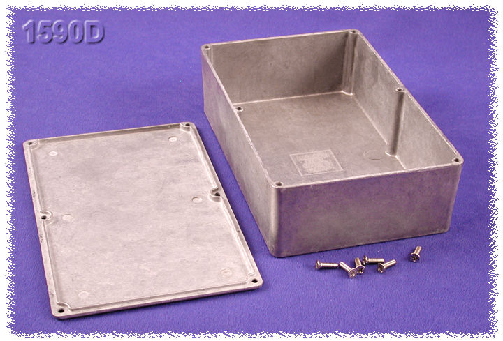
How about this :


http://www.hammondmfg.com/dwg.htm
http://parts.digikey.com/1/parts/7054-b ... 590dd.html
It would limit us to the 160x100 size anyway, but having a top loader would make using bus bars and bolting them to the sides of the case possible unlike a MS style endways case. You could potentially use one end of the board for FET mounting too. It would be really easy to seal such a case with either a gasket and/or some silicone sealant also unlike the MS style cases.
As a bonus for those wanting to expand you can get higher ones :
http://www.hammondmfg.com/jpeg/1590D_IB.jpg
http://www.hammondmfg.com/jpeg/1590E_IB.jpg
It's just AN option, there is a case thread that someone should bump and we should all review too.
I can get them in NZ and here from farnell, and as a bonus, they can be had flanged for mounting purposes :

Fred.
http://www.hammondmfg.com/dwg.htm
http://parts.digikey.com/1/parts/7054-b ... 590dd.html
It would limit us to the 160x100 size anyway, but having a top loader would make using bus bars and bolting them to the sides of the case possible unlike a MS style endways case. You could potentially use one end of the board for FET mounting too. It would be really easy to seal such a case with either a gasket and/or some silicone sealant also unlike the MS style cases.
As a bonus for those wanting to expand you can get higher ones :
http://www.hammondmfg.com/jpeg/1590D_IB.jpg
http://www.hammondmfg.com/jpeg/1590E_IB.jpg
It's just AN option, there is a case thread that someone should bump and we should all review too.
I can get them in NZ and here from farnell, and as a bonus, they can be had flanged for mounting purposes :
Fred.
DIYEFI.org - where Open Source means Open Source, and Free means Freedom
FreeEMS.org - the open source engine management system
FreeEMS dev diary and its comments thread and my turbo truck!
n00bs, do NOT PM or email tech questions! Use the forum!
The ever growing list of FreeEMS success stories!
FreeEMS.org - the open source engine management system
FreeEMS dev diary and its comments thread and my turbo truck!
n00bs, do NOT PM or email tech questions! Use the forum!
The ever growing list of FreeEMS success stories!
-
davebmw
- LQFP144 - On Top Of The Game
- Posts: 331
- Joined: Sun Jul 13, 2008 2:58 pm
- Location: South Wales, UK
Re: PCB layout
Ok, I have found my crayolas and sketched something out to show what i think would be a good way to go with the PCB layout. I have used (just as an example the BMW Bosch 88 way DME connector I will be using this for my version but we will have to find a suitable, durable and weather proof version for the generic board that is reasonably priced and easy to source.
The PCB measures 160mm x 140mm would be double sided through plated with HASL finish, a mix of PIH and SMT parts i would suggest 1206 as a minimum SMT part size.
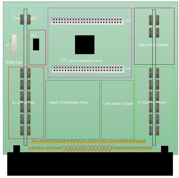
I have outlined areas that would give some idea of the arrangement of the circuit blocks.
red = 12 coil drivers TO220 on heatsink rail
Green = 12 injector drivers TO220 on HS Rail
Blue/Green = all inputs that require conditioning or isolation are sorted here
crappy yellow = Low power outputs for opto isolated or low power buffered outouts, eg tacho, indicators, external equipment etc etc.
Brick red = High current drivers for VANOS, VVT, PWM Fuel pump, PWM fan, water spray, etc
Brown = Idle Air Control bipolar stepper driver, this can be used for stepper motor, 2 or 3 wire PWM idle speed control.
Light blue = CPU area and sensor power supplies
Pink area = The CPU area with all required perhipherals, comms, clocks, etc there are 2 x 50 way headers to allow expansion to a top mounted PCB which would allow for massive facility for growth. or you could plug in the TA PCB and talk via CAN to have a dual CPU setup, I can't think why the hell you would want 2 XDP processors in the ecu but if the feature is there you may want to use it for massive data logging functions.
Of course the main reason for these 2 50 ways is an either or design. if you already have the TA card you just plug it in or if you can get the chip and associated parts and populate the area.
I have stuck a battery in there for battery backed RAM, I like the idea of RAM on board to store the adaptive data from the MCU rather than killing the flash with multiple writes.
Any suggestions???
The PCB measures 160mm x 140mm would be double sided through plated with HASL finish, a mix of PIH and SMT parts i would suggest 1206 as a minimum SMT part size.
I have outlined areas that would give some idea of the arrangement of the circuit blocks.
red = 12 coil drivers TO220 on heatsink rail
Green = 12 injector drivers TO220 on HS Rail
Blue/Green = all inputs that require conditioning or isolation are sorted here
crappy yellow = Low power outputs for opto isolated or low power buffered outouts, eg tacho, indicators, external equipment etc etc.
Brick red = High current drivers for VANOS, VVT, PWM Fuel pump, PWM fan, water spray, etc
Brown = Idle Air Control bipolar stepper driver, this can be used for stepper motor, 2 or 3 wire PWM idle speed control.
Light blue = CPU area and sensor power supplies
Pink area = The CPU area with all required perhipherals, comms, clocks, etc there are 2 x 50 way headers to allow expansion to a top mounted PCB which would allow for massive facility for growth. or you could plug in the TA PCB and talk via CAN to have a dual CPU setup, I can't think why the hell you would want 2 XDP processors in the ecu but if the feature is there you may want to use it for massive data logging functions.
Of course the main reason for these 2 50 ways is an either or design. if you already have the TA card you just plug it in or if you can get the chip and associated parts and populate the area.
I have stuck a battery in there for battery backed RAM, I like the idea of RAM on board to store the adaptive data from the MCU rather than killing the flash with multiple writes.
Any suggestions???
93'BMW 325is M50B25TU, Rebuilt 06/06, JE10.5:1, polish&port. Scorpion BB, K&N CAI, TEJ21 WBO2, '07 M3 Evo 18" 225F, 255R, EBC Kevlar, Bilstien Sprint, Polyflex. Head rebuild Oct'08, OEM+FSE FPR, MS2v3.0_DJB Custom, Extra 2.0.1
Re: PCB layout
There is an onboard eeprom for writing state data for the next run, otherwise the board could be constant powered and code written to place it into sleep mode where the only draw would be quiescent current from the regulator and a tiny ram holding current for the cpu.
You forced me to think about the serial connection. After thinking I've realised that it's not at all a big deal to desolder the db9 from the TA board and run a ribbon to a suitable convenient location. Same goes for those wanting USB connectivity (me included). Not caring about facing the DB9 outward opens up a bit more scope for rearranging things.
If you want to have a stepper driver, would it not be best to use full sized FETs backed by a driver chip? Or can you get suitably powerful and reliable chips to do this? I know for a fact the MS chip is unsuitable and unreliable in real world use most of the time, just like vb921s suck.
I like your dual cpu socket idea. I can't see any problems with it at all actually, but there could be something. One thing is for sure, you couldn't have it TA compatible for the purposes of main CPU (leaving the cpu bits on board unpopulated) AND have it TA compatible with respect expansion to two CPUs. I think standardising around the TA footprint is a good thing for expansion though. It provides I/O connectivity to nearly all the CPU pins, is compact, and can be made durable with suitable components.
Why only 4 drivers in the high current section? I assume you intend to have only high Z capability on this board? I can't be sure, but I suspect that there will be excess power dissipated if you run 12 low Z injectors in PWM mode on that small a heat sink. Speaking of heat generation, do you intend that these bars will just hang like that or be fixed to the case for further dissipation?
Nice drawing :-)
Fred.
DIYEFI.org - where Open Source means Open Source, and Free means Freedom
FreeEMS.org - the open source engine management system
FreeEMS dev diary and its comments thread and my turbo truck!
n00bs, do NOT PM or email tech questions! Use the forum!
The ever growing list of FreeEMS success stories!
FreeEMS.org - the open source engine management system
FreeEMS dev diary and its comments thread and my turbo truck!
n00bs, do NOT PM or email tech questions! Use the forum!
The ever growing list of FreeEMS success stories!