injectors - [56k beware page 2]

From DIY contraptions to sophisticated FreeEMS-specific designs! Plus general hardware development!
User avatar
jharvey
1N4001 - Signed up
Posts: 1607
Joined: Tue Jun 10, 2008 5:17 pm

Re: injectors

Post by jharvey »

Fred wrote:
it shows .01 ohm as a shunt resistor.
Nope, no such part in fig 17. No point looking at the other diagrams either as it's an ignition driver and they are test setups anyway.
My bad, I had both injector and ignition data sheets open. I grabbed the wrong number. The injector sheet had the same test setup, but as you note, that's not what you had in mind.
Fred wrote:
If we're going to hope for current sense in the first freeEMS board
I'm hoping that you don't try and do that :-) For non P&H injectors we don't want or need the extra complication.
I don't think this is really a big deal. The current sense .01 resistor is as simple as adding to blank pads on the PCB. Those that aren't looking for this capability, will simply solder an old lead across it making it a 0 resistor. I'm sure that with the first go at it, we'll want the ability to look at that signal.
Fred wrote:
then I should probably recommend we add space for a hall sensor. Much less complicated hardware wise and costs about the same dollar wise.
Less complicated than what? Hall sensors interface directly with the CPU (via basic diode/resistor/capacitor protection and filtering) and live in the engine bay, not on the board. For Hall, not a lot needs to be done, for VR we need a conditioner, but that doesn't belong in this thread.
Hall sensors that run saturated produce nice square waves that are good for different pickups. Hall sensors don't need to be run saturated, and can produce analog signals based on the amount of flux that is crossing them. Putting a hall sensor on a trace will allow you to measure the flux, which coincides with the current running in that trace.

A prepackaged version can be found here. http://www.allegromicro.com/en/Products ... sensor.asp However, if you calibrate it yourself, you can same some good cash, by using a much cheaper hall sensor.

I've started playing with QUCS to look at some injector parameters. I tried to attach the files, but it didn't work. Said board quota has been reached. Probably better for these spice files to go to the CVS instead.
Image

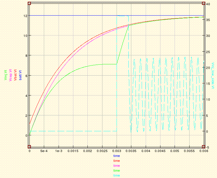
This graph shows some ringing problems caused by a tank circuit. This is one of the reasons why shunting the inductive current is important. Also note the diode causes the 3ms to 3.5ms issue. Oh the diode, perhaps I should post the schematic.

Image

I used a switch for now rather then a FET or IGBT to keep it simple. I also simulated the reverse diode with the Dclamp diode, it's set at 36v reverse bias. I choose 25mF to match the 25mH of the inductor because it felt like that would balance out. As you can see that doesn't matter much. It still rings significantly.

Other notes I expect the injector resistance due to the wire length to be about 15 ohms. That resistance is mixed with the inductance, so I split it and put it on both sides of the inductor to simulate a more real world inductor. It would probably be better if there were several inductors and resistors, but this should work OK for now.

Rbat = internal resistance of a battery, calculated by 240 cold cranking amps with 12V.
Rcap = randomly picked to include resistance due to wire and cap plates.
Cballance = cap that helps with the inrush current when you open the injector.
Rinj = half the injector DC resistance
R1 = the other half of the resistance, oops should have renamed.
L2 = the injector inductance

Some parameters I'm looking to learn, what is the typical period and duty cycle of the injectors? Have those kinds of parameters been determined yet? I'm also assuming it's a fixed period.
davebmw
LQFP144 - On Top Of The Game
Posts: 331
Joined: Sun Jul 13, 2008 2:58 pm
Location: South Wales, UK

Re: injectors

Post by davebmw »

Hi Guys after setting up our little experiment with 4 injectors on a nissan 200ZX CA18DET rail using 2 injectors, 1 pure DC 0 and 1 pulsed at 2ms open and 10mS closed and one with 1mS PWM prime and 100uS pulse 900 uS pwm hold at 70% and 10mS closed.
my findings are not encouraging.
after 100000 squirts only 0.1% increase in ejected volume.
the only conclusive thing is the the delta C in the injector and ejected liquid showed an increase of 1.5 deg C in the injector and 0.2 deg C in the liquid.
I think this is a red herring.
Nice thought though. :)
93'BMW 325is M50B25TU, Rebuilt 06/06, JE10.5:1, polish&port. Scorpion BB, K&N CAI, TEJ21 WBO2, '07 M3 Evo 18" 225F, 255R, EBC Kevlar, Bilstien Sprint, Polyflex. Head rebuild Oct'08, OEM+FSE FPR, MS2v3.0_DJB Custom, Extra 2.0.1
User avatar
jharvey
1N4001 - Signed up
Posts: 1607
Joined: Tue Jun 10, 2008 5:17 pm

Re: injectors

Post by jharvey »

jharvey wrote:I don't like the term flyback. I've only seen that in MS land, and I feel it shows electrical ignorance. This circuit shunts current, so I recommend we call it ISC for Inductive (or Injector) Shunt Circuit. I think that will help separate the Engineers from the mechanics. Thoughts?
I've got a minute, guess I'll reply to myself. I know the circuit uses a diode often called a flyback diode, snubber diode, freewheel diode, ect. I generally don't title a circuit based on the components that are in it. Instead I title based on what it does.

For example a wire connected accross a battery would be called a short circuit and not a wire circuit or a battery circuit.

Well looks like lunch is over, guess it's back to the bump and grind.
User avatar
Fred
Moderator
Posts: 15433
Joined: Tue Jan 15, 2008 2:31 pm
Location: Home sweet home!
Contact:

Re: injectors

Post by Fred »

Thank you for the info on hall sensing on a PCB Mr Harvey :-) You learn something every day!

Thanks for the injector tests Dave, that sounds about right. The opposite is not true however :

If you fail to provide enough grunt such that your FETs are current limiting during the opening phase (low or high z) then opening times will be slower and inconsistent. Hence sizing the FET correctly such that it does not even come close to limiting during normal operation is a good idea/essential.

Fred.
DIYEFI.org - where Open Source means Open Source, and Free means Freedom
FreeEMS.org - the open source engine management system
FreeEMS dev diary and its comments thread and my turbo truck!
n00bs, do NOT PM or email tech questions! Use the forum!
The ever growing list of FreeEMS success stories!
User avatar
jharvey
1N4001 - Signed up
Posts: 1607
Joined: Tue Jun 10, 2008 5:17 pm

Re: injectors

Post by jharvey »

Now I've got it modeled with both snubbing cap and snubbing diode.

Image

Image

R1 is there to over come a minor bug. It couldn't handel two switches at the same node, so I added the resistor to change the node up a bit.

Notice the ringing is gone, Cap values are feasable, and the Zener isn't required any more. Still a good idea incase the Dsnub breaks however.

Another note, it's taking aprox 3-4 ms to power on enough to get the injector to turn on. That's about twice what the injector test folks posted. I'm trying to find one of my calculators that can do e^(R/L), but it seems I've miss placed it. I believe there has to be some kind of difference from this spice vs what that guy posted about his findings. I don't think you can get the responces noted with 15ohm and 25mH.

Any one know the ball park capacitance and or series inductance of a battery? Right now this spice works the same for higher frequencies as it does for lower frequencies. The higher frequencies won't have the same Rbat value because of inductive load losses. I'd like to model them as well.
User avatar
jharvey
1N4001 - Signed up
Posts: 1607
Joined: Tue Jun 10, 2008 5:17 pm

Re: injectors

Post by jharvey »

Hmmm, so I'm getting to learn about the transconductance coefficient's (KP) of MOSFET's and such. I was having a pinch of trouble with the SPICE because this parameter was set incorrectly with the MOSFET. The default FET only allowed nA and some mA, not several amps like we are looking for. The data sheets so far haven't directly mentioned what this would be, so I'll have to guess. I found this page to help me out.

http://eesun.free.fr/MOSMODEL1/index.html

It has a java thing that allows you to put in values, I changed KP 140 to KP 310000 and got a nice graph that showed 8a at 5V. The QUCS default FET was 2e-5, but I still don't know what value QUCS wants. So I guess it's time for a sample model. I'm looking for about 5V 8A.

Image Image

So I'd say that a KP of around 31 isn't extremely far off. Especially with a high impedance injector modeled, it only wants around an amp. I updated the injector schematic to include the FET as the driver and give it a digital input.

Image
Image

So I'm back to inquiring about what the period and duty is going to be. For simplicity, I might choose a 100mS period and I would expect an on duty of 5mS (or 5%) to produce nearly no fuel.

I'm surprised to see the model acting this way. The post that started this thread showed a min duty of about 2 to 2.5mS about half what I'm showing in spice. Anyone know which one is more accurate? I'd guess the web page is more typical. Any thoughts about why? Perhaps there is some tuning I can do.
User avatar
Fred
Moderator
Posts: 15433
Joined: Tue Jan 15, 2008 2:31 pm
Location: Home sweet home!
Contact:

Re: injectors

Post by Fred »

The injector on time min will be about 1ms and on time max for most people around 20ms

Period will be min of 10 - 15ms and max of 100 - 200ms

EDIT : on duty for normal voltage is in the 0.5 - 1.5ms range (dead time, no fuel) typical fuel requirements at idle are around the 1ms range.

I hope that helps :-)

Fred.
DIYEFI.org - where Open Source means Open Source, and Free means Freedom
FreeEMS.org - the open source engine management system
FreeEMS dev diary and its comments thread and my turbo truck!
n00bs, do NOT PM or email tech questions! Use the forum!
The ever growing list of FreeEMS success stories!
User avatar
Fred
Moderator
Posts: 15433
Joined: Tue Jan 15, 2008 2:31 pm
Location: Home sweet home!
Contact:

Re: injectors

Post by Fred »

You may want to model this between 6 Volt at the batter and 14.4 Volt at the battery.

You will lose a little through wiring etc obviously, but that's almost negligible. I have a spread sheet of opening times, I'll email it to you. It's probably not perfect, but is probably fairly good.

Fred.
DIYEFI.org - where Open Source means Open Source, and Free means Freedom
FreeEMS.org - the open source engine management system
FreeEMS dev diary and its comments thread and my turbo truck!
n00bs, do NOT PM or email tech questions! Use the forum!
The ever growing list of FreeEMS success stories!
User avatar
jharvey
1N4001 - Signed up
Posts: 1607
Joined: Tue Jun 10, 2008 5:17 pm

Re: injectors

Post by jharvey »

Here are some interesting sims. I have made both Diode snubbed and Cap snubbed for the injector driver. I've also added an R value for the injector connection. Here are some snap shots with a 10 ohm resistance on the injector connector.

Image
Image

Notice the injector current is about half, right out of the gate, it should be about .8 to 1 amp. Also note the charge curve has about the same profile yet less amplitude, but the discharge profile is much slower such that it doesn't make it to 0 amps. So the injector(s) would stay open much longer if you have a bad connection. Not quite what I would have expected based on gut feel.

Fred you inquired about 6VDC w/ good injector connections here you go
Image
Image

And now for comparison the 14VDC w/ good injector connections.

Image
Image

I think I like the Diode snubbed version better. The charge and discharge profiles are about the same, and bad injector connections cause less of a problem.

I've also seen zeon lights as a snubber. That might work better then a diode because once is starts conducting it doesn't have that .7v drop, and you get some light from it. Thoughts?

http://www.rmcybernetics.com/projects/D ... driver.htm
User avatar
Fred
Moderator
Posts: 15433
Joined: Tue Jan 15, 2008 2:31 pm
Location: Home sweet home!
Contact:

Re: injectors - [56k beware page 2]

Post by Fred »

Jared,

Anything you do that snubs the back emf from the injector slows it's close down. A large part of the point of the autoprotected FETs is that they have a fairly high clamping voltage (50 or so) and consequently A protect themselves from back emf, and B allow the injector to close faster. If we start trying to smooth and silence the whole thing we will just slow the injector down and cause major troubles.

As interesting as this is, I don't understand why it is all necessary. The reason for using the simple devices is to make it 3 components : CPU > 1k resistor > FET > Injector > +12V

With high Z injectors that really is all you need :-)

Fred.
DIYEFI.org - where Open Source means Open Source, and Free means Freedom
FreeEMS.org - the open source engine management system
FreeEMS dev diary and its comments thread and my turbo truck!
n00bs, do NOT PM or email tech questions! Use the forum!
The ever growing list of FreeEMS success stories!
Post Reply