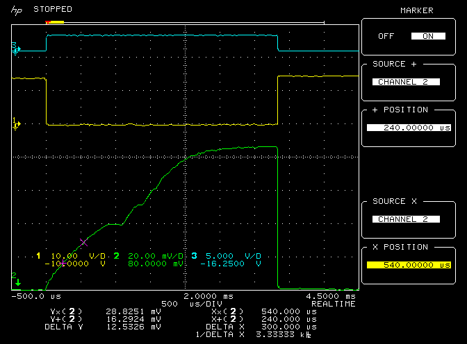
tpsretard had the link I was looking for. I was looking for the typical / ball park uH of an injector, also I was looking for the curve that shows the bumps when the injector hits bottom.

This curve shows this isn't quite the same as a solenoid, but is quite close. The pin absorbs some of the energy, changing the curves some. I see the bounce on the back of the pin as it opens. When it comes to closing the injector, it's possible we could give it a soft landing if we give it some extra energy just before it bottoms out, but I suspect the spring and other such mechanical aspects typically take care of that mostly. However, letting the field collapse uncontrolled, with the fuel pressure behind it, I suspect EssEss is right. I would guess that, it shortens the injectors life. I would also guess that if we have a pressure meter on our fuel, we would see some large pressure spikes from "water hammer". I wonder what the resonant frequency of this pin would be. Hopefully not near 5khz or 6khz. Those frequencies or near those frequencies could trigger the knock sensor when we eventually have it.
On the opening side of the cycle, I can't help but feel that the change in mH could correlate to the inertia of the pin. This fellow shows it as 32.8 mH off, 23.5 mH when on. So the pins energy was equivalent to about 9.3mH. If we knew the inertia of the injector, we could soften the open, and soften the close of the injector, as well as predicted dead bands, and other parameters.
While we can approximate the dead band, and mostly remove it with software delays and preemptive turn on times, other features are much harder to do in basic software, or hardware. Like softening the on and off times, or preventing noise by decreasing water hammer effects. That's part of the reason why I'm a bit more of a fan of piping current sense data back to the brain, and letting the brain control these things in software.
I suspect hardware P&H circuits have some problems in the 1 to 2 mS range. The drive hard, then decrease your drive approach at these times would likely cause the injector to vary it's fuel squirt. Even if it doesn't completely close, I would bet as the pin bounces back, it limits the flow. I see software config of these parameters as very handy.
Any one interested in attempting to make an equation for the injector? I can't help but want to see an equation, that when plugged into a spread sheet program will produce the same curve shown in the above picture.
I think it's kind of interesting to see the low impedance injectors don't appear to bounce.