
Can you detail any single ONE aspect of code, anything at all, that would NOT run in an ISR ?
I don't understand your diagram with respect to what needs to be achieved. There are two chunks of code that need to exist to do two slightly separate but inter related work. Nothing else needs to be done, what exactly do you propose does need to be done outside the ISRs and what exactly is it?
Help me out :-)
Wheel decoder/scheduler architecture
Re: Wheel decoder front/backend interface definition
DIYEFI.org - where Open Source means Open Source, and Free means Freedom
FreeEMS.org - the open source engine management system
FreeEMS dev diary and its comments thread and my turbo truck!
n00bs, do NOT PM or email tech questions! Use the forum!
The ever growing list of FreeEMS success stories!
FreeEMS.org - the open source engine management system
FreeEMS dev diary and its comments thread and my turbo truck!
n00bs, do NOT PM or email tech questions! Use the forum!
The ever growing list of FreeEMS success stories!

Re: Wheel decoder front/backend interface definition
I agree with Fred, I don't see how that's going to be representative of real code. If you go through the exercise of putting real stuff in that diagram structure, you'll end up with something much closer to Fred's diagram if you want to have something that will have a chance to run in real time.
If you have something specific to support this structure, I too would be interested in seeing it.
Jean
If you have something specific to support this structure, I too would be interested in seeing it.
Jean

Re: Wheel decoder front/backend interface definition
Where do you plan to determine what tooth the ign/inj events are triggered off of and calculate the time, to schedule a timer for, between the trigger tooth event and the actual event? Surely not in ISR! that's not speaking of all kinds of time/processing power intensive time calculations and stats that need to be performed, that'll be needed for even primitive form of tach signal filteringAdmin wrote:Can you detail any single ONE aspect of code, anything at all, that would NOT run in an ISR ?
EDIT: Now i've realized that i've been bunching up the decoder and the scheduler, after reading this Fred's thread. Will update the diagram appropriately
Legal disclaimer for all my posts: I'm not responsible for anything, you are responsible for everything. This is an open and free world with no strings attached.
Re: Wheel decoder front/backend interface definition
I don't see how scheduling the timer can be anywhere other than in the ISR. However, you're right that some of the other computations should be done outside but some will need to be done there because they are needed as quickly as possible.ababkin wrote:Where do you plan to determine what tooth the ign/inj events are triggered off of and calculate the time, to schedule a timer for, between the trigger tooth event and the actual event? Surely not in ISR! that's not speaking of all kinds of time/processing power intensive time calculations and stats that need to be performed, that'll be needed for even primitive form of tach signal filteringAdmin wrote:Can you detail any single ONE aspect of code, anything at all, that would NOT run in an ISR ?
But that still doesn't make your structure the right one in my mind. What should be done is to divide Fred's backend block into 2 sections: one outside the ISR and not connected to the hardware and the ISR part connected to the hardware. In a sense, these 2 blocks are your hardware and hardware abstraction layer. And I don't see any generic wheel decoder ISR being requires or even desired. Any wheel decoder ISR code will be wheel specific even if there is a generic X-Y wheel decoder in which case the ISR code will be specific to this type of wheel. Some code will be reusable between the different wheel-specific code but not as a generic block, in my opinion.
Jean
Re: Wheel decoder front/backend interface definition
BTW, i've revised the diagram again and started the block description/summary.
As discussed earlier in this thread, it would be a very good idea (only if it's possible of course) to only have a specific-wheel-runtime-data-configurable generic decoder vs. having different code backends to have to specifically compile against.
Never said it should be otherwise. Sorry if i wasn't clear - i meant 'calculate the time for timer scheduling'jbelanger wrote: I don't see how scheduling the timer can be anywhere other than in the ISR.
ababkin wrote:...and calculate the time, to schedule a timer for, between the trigger tooth event and the actual event...
The generic wheel decoder block is simply an embodiment of my suspicion of a common code existence among the variety of possible implementations for any possible wheel configurations. (in short: i don't like code duplication)jbelanger wrote: And I don't see any generic wheel decoder ISR being requires or even desired. Any wheel decoder ISR code will be wheel specific even if there is a generic X-Y wheel decoder in which case the ISR code will be specific to this type of wheel. Some code will be reusable between the different wheel-specific code but not as a generic block, in my opinion.
As discussed earlier in this thread, it would be a very good idea (only if it's possible of course) to only have a specific-wheel-runtime-data-configurable generic decoder vs. having different code backends to have to specifically compile against.
Legal disclaimer for all my posts: I'm not responsible for anything, you are responsible for everything. This is an open and free world with no strings attached.
Re: Wheel decoder front/backend interface definition
Sorry about the misunderstanding.ababkin wrote:BTW, i've revised the diagram again and started the block description/summary.
Never said it should be otherwise. Sorry if i wasn't clear - i meant 'calculate the time for timer scheduling'jbelanger wrote: I don't see how scheduling the timer can be anywhere other than in the ISR.ababkin wrote:...and calculate the time, to schedule a timer for, between the trigger tooth event and the actual event...
In my view, the generic wheel decoder code is not going to be in the ISR but outside (again as per Fred's diagram). For performance, I don't see anything other than specific wheel code being put in the ISR and that code definitely not seeing the hardware through an abstraction layer. Everything has to be as direct as possible.ababkin wrote:The generic wheel decoder block is simply an embodiment of my suspicion of a common code existence among the variety of possible implementations for any possible wheel configurations. (in short: i don't like code duplication)jbelanger wrote: And I don't see any generic wheel decoder ISR being requires or even desired. Any wheel decoder ISR code will be wheel specific even if there is a generic X-Y wheel decoder in which case the ISR code will be specific to this type of wheel. Some code will be reusable between the different wheel-specific code but not as a generic block, in my opinion.
As discussed earlier in this thread, it would be a very good idea (only if it's possible of course) to only have a specific-wheel-runtime-data-configurable generic decoder vs. having different code backends to have to specifically compile against.
Also, I have a hard time seeing what you want to put in that abstraction layer. As Fred said, there are 2 dedicated pins used for IC and these are not going to change. In any case if they were to change, you'd have to change the ISR and/or the ISR declaration because the ISR is tied to the pin (or more correctly to the timer).
Jean
Re: Wheel decoder front/backend interface definition
Yes, in the ISR if profiling reveals that it is indeed possible to do so. There are some significant advantages to be realised by doing this, but like both of you I suspect maybe it can't be done. Unlike (both of?) you, I intend to give it a try! Being from that little dot down under I have this attitude known as "can do" :-) I try to put it into everything I try to do.ababkin wrote:Where do you plan to determine what tooth the ign/inj events are triggered off of and calculate the time, to schedule a timer for, between the trigger tooth event and the actual event? Surely not in ISR!
If it doesn't work out, then we learned something, if it does, then we score a big win! Simple.
I suspect you are right, but I still hope you are wrong, the power from being able to swallow a user config and just work is immense. Still, for soooo many reasons, I doubt it, but once again, worth a shot.jbelanger wrote:And I don't see any generic wheel decoder ISR being requires or even desired. Any wheel decoder ISR code will be wheel specific even if there is a generic X-Y wheel decoder in which case the ISR code will be specific to this type of wheel. Some code will be reusable between the different wheel-specific code but not as a generic block, in my opinion.
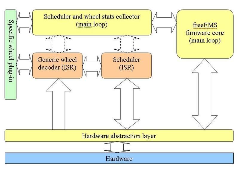
with regards this latest diagram (which I am now caching because they vanish so fast :-p) :
http://i260.photobucket.com/albums/ii15 ... iagram.jpg
IMO the wheel/trigger/RPM/engine position stuff IS CORE FreeEMS code even if it changes from wheel to wheel.
the "hardware abstraction layer" needs to go
the line from the right hand "main loop" to the hardware needs to go (what does it care about hardware? with regards wheels/triggers/etc i mean)
the line from the scheduler to the hardware needs to be unidirectional
none of the scheduler will be in the "main loop"
if generic becomes real, the scheduler probably needs information from that too
any statistics collection with regard to wheel errors etc will need to be done in the RTI for good accuracy, but doing it in the main loop and reading a time variable is also possible.
the only thing that the decoder and scheduler will get from outside is config and maybe some variables
the only things they will feed back are status and variables
Of course, all this pertains to NOT using the XGATE (just yet) and KISS principle of least cleanest code to do a given job.
Admin.
DIYEFI.org - where Open Source means Open Source, and Free means Freedom
FreeEMS.org - the open source engine management system
FreeEMS dev diary and its comments thread and my turbo truck!
n00bs, do NOT PM or email tech questions! Use the forum!
The ever growing list of FreeEMS success stories!
FreeEMS.org - the open source engine management system
FreeEMS dev diary and its comments thread and my turbo truck!
n00bs, do NOT PM or email tech questions! Use the forum!
The ever growing list of FreeEMS success stories!
Re: Wheel decoder front/backend interface definition
replying on the comments:
(i numbered them for you)
1. "freeEMS core" is a misnomer, i agree. I meant the rest of the freeEMS firmware code (not including the other blocks in the diagram). Please suggest a good name for this block.
2. Hardware abstraction layer (HAL): guys, please don't think of this as an extra overhead and nothing else. This layer can be implemented as a bunch of macros and thus will be transparent during the runtime, i.e no runtime overhead (but no runtime configuration benefits this way). I just hate hardcoding stuff! Just keep the layer as a placeholder for a decision later on, on how we are going to deal with clean mapping of IO registers ( which will be quite useful with all the extra IO and custom hardware mapping of those in the user customized hardware ). Indeed, decoder ISR can bypass HAL, as there are really only 2 (?) external interrupt pins.
3. This line/arrow basically signifies whatever interaction "the rest" of the firmware is having with the hardware (ADCs, etc..) not decoder/scheduler specific.
4. Scheduler ISR schedules timer interrupts as well as handles them to fire off an event (see the block description)
5. Sure, you'll/we'll experiment with putting sched-related timecalcs inside the ISR, but personally i have VERY slight hope for this to work adequately. (there is a reason why ISRs were rewritten in asm by certain individuals ). So until it is a solid and proven decision to have all this inside ISR, please let this main-loop block exist.
6. I think you are right on that one, i will revise
7. by statistics i mostly meant calculating tooth-time-period, deltas, etc. Again, you might be able to do it in ISR, but i'm highly doubtful
8 and 9: YES! that's why the arrows are dashed => indirect synchronized
Alex
(i numbered them for you)
More clarification on the diagram: this diagram represents the whole of the firmware. It just details out the decoder/scheduler portion of it somewhat more. This was the point of the diagram.Admin wrote: 1. IMO the wheel/trigger/RPM/engine position stuff IS CORE FreeEMS code even if it changes from wheel to wheel.
2. the "hardware abstraction layer" needs to go
3. the line from the right hand "main loop" to the hardware needs to go (what does it care about hardware? with regards wheels/triggers/etc i mean)
4. the line from the scheduler to the hardware needs to be unidirectional
5. none of the scheduler will be in the "main loop"
6. if generic becomes real, the scheduler probably needs information from that too
7. any statistics collection with regard to wheel errors etc will need to be done in the RTI for good accuracy, but doing it in the main loop and reading a time variable is also possible.
8. the only thing that the decoder and scheduler will get from outside is config and maybe some variables
9. the only things they will feed back are status and variables
1. "freeEMS core" is a misnomer, i agree. I meant the rest of the freeEMS firmware code (not including the other blocks in the diagram). Please suggest a good name for this block.
2. Hardware abstraction layer (HAL): guys, please don't think of this as an extra overhead and nothing else. This layer can be implemented as a bunch of macros and thus will be transparent during the runtime, i.e no runtime overhead (but no runtime configuration benefits this way). I just hate hardcoding stuff! Just keep the layer as a placeholder for a decision later on, on how we are going to deal with clean mapping of IO registers ( which will be quite useful with all the extra IO and custom hardware mapping of those in the user customized hardware ). Indeed, decoder ISR can bypass HAL, as there are really only 2 (?) external interrupt pins.
3. This line/arrow basically signifies whatever interaction "the rest" of the firmware is having with the hardware (ADCs, etc..) not decoder/scheduler specific.
4. Scheduler ISR schedules timer interrupts as well as handles them to fire off an event (see the block description)
5. Sure, you'll/we'll experiment with putting sched-related timecalcs inside the ISR, but personally i have VERY slight hope for this to work adequately. (there is a reason why ISRs were rewritten in asm by certain individuals
6. I think you are right on that one, i will revise
7. by statistics i mostly meant calculating tooth-time-period, deltas, etc. Again, you might be able to do it in ISR, but i'm highly doubtful
8 and 9: YES! that's why the arrows are dashed => indirect synchronized
Alex
Legal disclaimer for all my posts: I'm not responsible for anything, you are responsible for everything. This is an open and free world with no strings attached.
Re: Wheel decoder front/backend interface definition
DIYEFI.org - where Open Source means Open Source, and Free means Freedom
FreeEMS.org - the open source engine management system
FreeEMS dev diary and its comments thread and my turbo truck!
n00bs, do NOT PM or email tech questions! Use the forum!
The ever growing list of FreeEMS success stories!
FreeEMS.org - the open source engine management system
FreeEMS dev diary and its comments thread and my turbo truck!
n00bs, do NOT PM or email tech questions! Use the forum!
The ever growing list of FreeEMS success stories!
Re: Wheel decoder front/backend interface definition
1. Accessories? "main loop"?
2. The thing is, because of the high chance of all the code being different wheel to wheel, as in ALL the code being different, how is it unclean and unnice to just swap in a whole .c file? at the worst you might need to fiddle the ISR table in main.c and add some more "classes" (help me out, whats the word for a source file in C, just source file?) and a sprinkling of extra config (for your particular oddball release)
3. Really, the way this is likely to end up structured is : separate wheel/inject/ignite code and a large structure of serial/feature/GP/port management/logging/etc code. The two will be pretty much unrelated, i.e. rip out one encoder and drop in another without affecting anything else in the code at all.
4. Running when an ISR occurs is hardly taking an input from the code. The sched and decode are in the same ISR and run sequentially at the same time, the decode reads hardware and writes vars, the sched reads vars and writes hardware, hence, unidirectional.
5. See the ideas I had in the other thread, you are probably right, but in any case, those are still just interfaced through global variables and used in the scheduler like any others... i.e. it has nothing to do with scheduling, only to do with pulsewidth, advance, dwell, etc.
7. This MUST be done in the ISR as it will be happening WAY more often than the "main loop" will be running.
8, 9, fair enough, the language barrier strikes again :-)
Admin.
DIYEFI.org - where Open Source means Open Source, and Free means Freedom
FreeEMS.org - the open source engine management system
FreeEMS dev diary and its comments thread and my turbo truck!
n00bs, do NOT PM or email tech questions! Use the forum!
The ever growing list of FreeEMS success stories!
FreeEMS.org - the open source engine management system
FreeEMS dev diary and its comments thread and my turbo truck!
n00bs, do NOT PM or email tech questions! Use the forum!
The ever growing list of FreeEMS success stories!