joey120373 wrote:If I could figure out a way to implement a wireless I2C link that might make for a cool combination, a single (optionaly) battery powered micro running a display and possibly data logging talking wirelessly to to one or more O2 sensors that are simply an SLC, voltage reg and a $2 transmitter......
Work has kept me busy so I had to shelf this project for awhile, however the last few days have been very productive.
Started playing with some very cheep radio boards, the NRF24l variants that can be had for a whopping $2 each.
Took a little fiddling to get them working but I am really impressed at how well they work.
I think the prototyping phase is over, I now have a fully functional wireless WBO2.
It consists of 2 arduino pro-minis, one 5 volt, one 3 volt. The 5volt mini interfaces and supplies power for the SLC OEM module, and the 3volt mini runs the 128x64 OLED (a cheep unit I got off eBay)
The radios are mini NRF24l+ units I also got off eBay, these are smaller than the standard units, they are about the size of a thumbnail. The only real drawback to these is the wiring header is .050inch not .1, makes connecting wires a tad tricky but not impossible.
I re-wrote the code for interfacing with the SLC module, cleaned it up a bit and modulised it, now I can choose how often I pole the different registers. I can now get an AFR update from the SLC around 1000 times a second. The OLED however is not able to update that fast with the little ATMEGA at 8mhz driving it, best I can get with the graphics I like is about 11 FPS, still quite useable, and actually noticeably faster than a name brand controller I have.
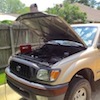
To test the radio I left the WB O2 sensor inside the cab of a truck ( doors closed ), Walked away with the display ( powered form a battery ) I was able to get over 50 yards away before I started loosing packets.
Now to get a case built for the display....
I have some boards in the way, there are 3 total.
One board is the same width as the SLC, but slightly longer, the SLC mounts to the back side of the board and the Pro mini mounts to the front side. There is input voltage protection and a 3.3v regulator for the radio transceiver, it also has a header to mount the radio.
There is another even smaller board designed to install on top of the pro mini, this is intended to be an optional input board, there are 4 protected analog input circuits and an opto-isolated digital input intended for RPM signal. There is also a 3 position DIP switch that can be used to address the unit, so up to 8 O2 sensors can be accessed from 1 display.
The 3rd board is for the display, it's a similar "sandwich" layout, with the OLED mounting on the front and its Pro mini mounting on the rear, it also has a micro USB, a micro SD card slot, LI-Po charging circuit and a radio header.
I haven't written any code yet for the data logging, but hopefully when the boards arrive I can get a couple assembled and do more development in that area.
Only have the power button mounted for now, but there will be 3 more added, these will be used to start and stop data logging and to scale the various inputs.