I design a really tiny core board with only vital clock circuit on. No voltage regulator, no other chips such as MAX232. Three 8x2 header design to fan out I/O pins as well as power pins. I only export A/B/P/T/AD. About my I/O board, I only finish drawing schema, probably unfinished gnd connections. To ease my installation, I design my I/O board Pin-to-Pin compatible with stock Bosch ECU, I decide to use the ripped off harness interface from the stock ECU. So I would like to hear your first glance comments before I layout the board, I'll tune FreeEMS to do a batch injection and 4 cylinder wasted spark on Citroen TU5JP/K engine. Also I would like to add a GPL license to my project, but I don't know how to do it. Please feel free to add one for me.
I want to be the first Chinese user running FreeEMS on real vehicle rather than on a simulator like JimStim, so never hesitate to criticize my board as much as you can
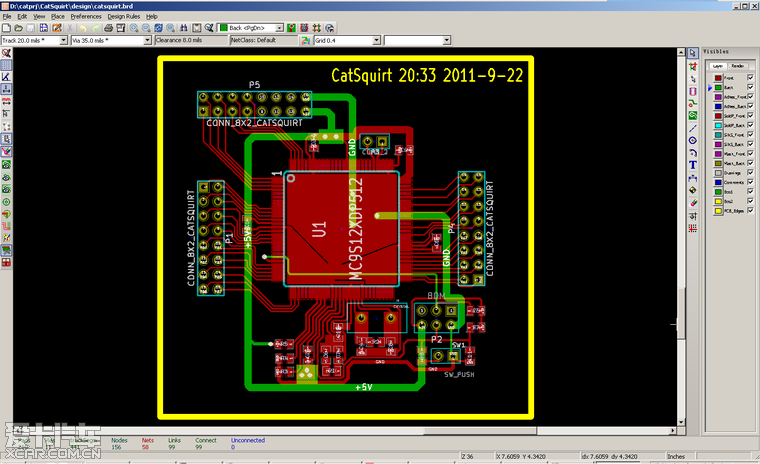
core board design
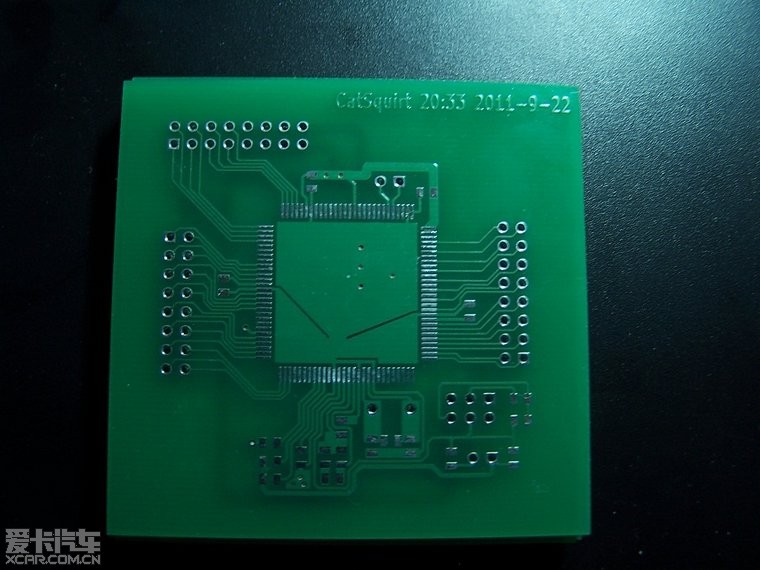
front view
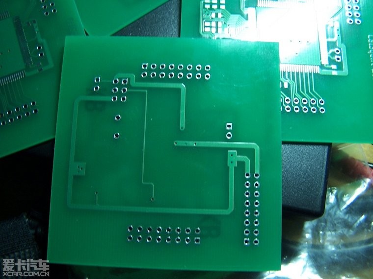
back view
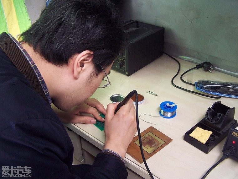
a friend of mine helps me solder S12XDP512, this chip probably was a ripped off stuff and a little difficult to solder
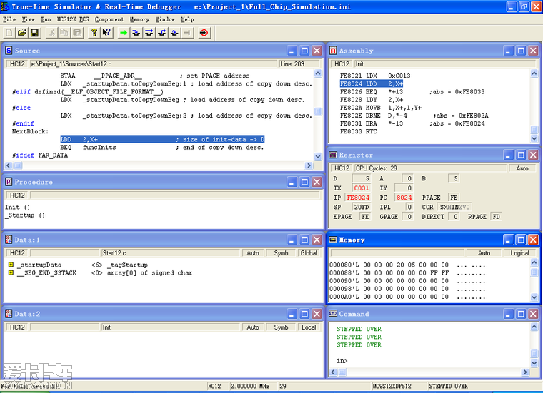
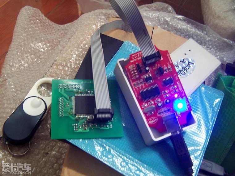
Finally, it works and responds to BDM
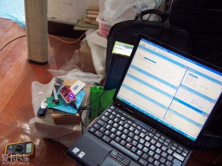
my favourite IBM T30 laptop and I bought another T30 to run debian exclusively
here we can see the chip is working, I only spent 5$ for S12XDP512