Page 5 of 6
Re: Building the Brains for a Budget Racer: Jaguar A7 #42
Posted: Fri Aug 05, 2016 10:22 pm
by Fred
Re: Building the Brains for a Budget Racer: Jaguar A7 #42
Posted: Sat Aug 06, 2016 1:26 am
by m2cupcar
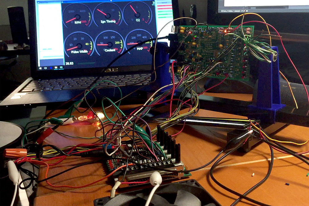
Stim test success. FreeEMS disco tech:
https://youtu.be/Vl1qlFi9fZA
Re: Building the Brains for a Budget Racer: Jaguar A7 #42
Posted: Sat Aug 06, 2016 11:57 am
by Fred
Idle! Totally forgot. Hook an odd numbered Port P (P1 is default, where range is 0-7) up to a spare FET (one of the LSD near the fan FET) and hook that FET to the PWM idle valve connector pin! Please :-)
Initial firmware will do random things to that valve, so just unplug it at first, but hopefully we can beat your start up attempt with some code. Worst case, unplug and wind throttle open a little to start with.
Open loop idle is easy to do and nice to have.
For initial testing, seeing that you're so keen on testing *everything*, they follow inputs, so in the case of P1, the coolant pot on the jimstim controls it with default firmware. You should be able to see your LED get brighter/dimmer with higher/lower CHT.
Re: Building the Brains for a Budget Racer: Jaguar A7 #42
Posted: Sat Aug 06, 2016 4:58 pm
by m2cupcar
P1 connected to LSD1-IN and LSD1 output lead connected. Will this IAC-capable fw be available at .../firmware/dev/images or elsewhere?
Re: Building the Brains for a Budget Racer: Jaguar A7 #42
Posted: Sat Aug 06, 2016 10:58 pm
by Fred
Good work. Eventually yes, but in the mean time, possibly not. You'll get a copy somehow, though.
Re: Building the Brains for a Budget Racer: Jaguar A7 #42
Posted: Sun Aug 07, 2016 5:39 am
by Fred
I just noticed that your Jaguar is the answer to life, the universe, and everything. This has to be a good luck omen.
Today's test session on no less than two FreeEMS powered vehicles, and a visit to three non-running FreeEMS powered engines, produced an interesting fact:
On Rob's R33, at least, the correlation between CHT and PWM out was roughly correct. IE, as temperature rose, RPM fell. Not correctly, but enough to not be too irritating. Might be vaguely usable as is :-)
This also means that we can easily check PWM idle table operation on Rob's R33, perhaps next weekend (it's rather loud). I look forward to making it happen. :-)
PS, those other photographs not posted here are hilarious :-D Nice work, team!
Re: Building the Brains for a Budget Racer: Jaguar A7 #42
Posted: Sun Aug 07, 2016 10:04 pm
by m2cupcar
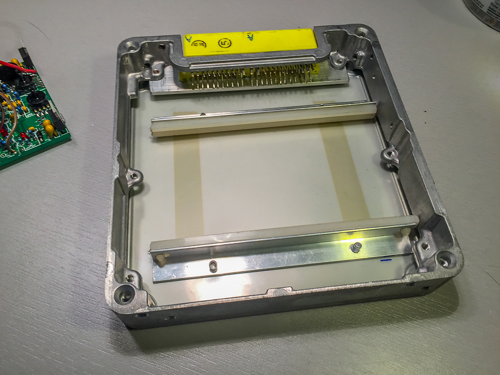
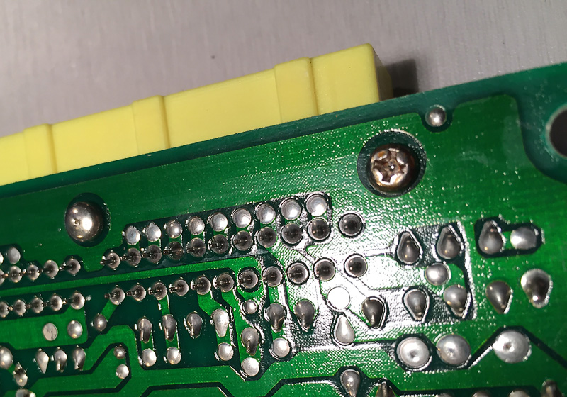
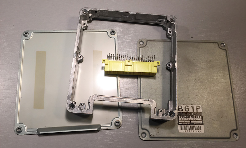
Case is ready after some clipping and wicking the solder out of the connector's pins and screws.
Re: Case progress
Posted: Thu Aug 11, 2016 1:47 pm
by m2cupcar
Re: Case Completed
Posted: Sat Aug 13, 2016 9:08 pm
by m2cupcar
Re: Building the Brains for a Budget Racer: Jaguar A7 #42
Posted: Sat Aug 13, 2016 11:38 pm
by Fred
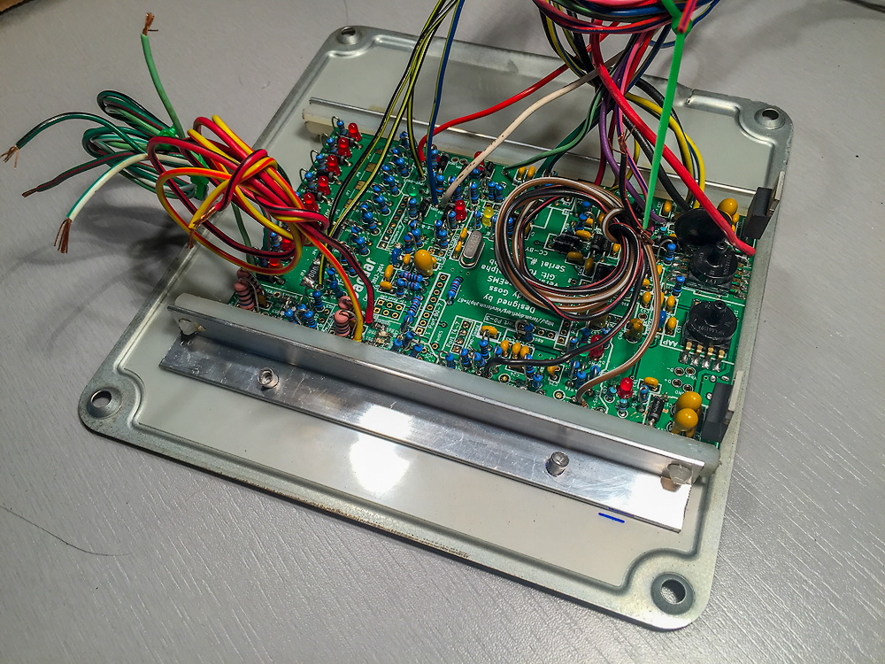
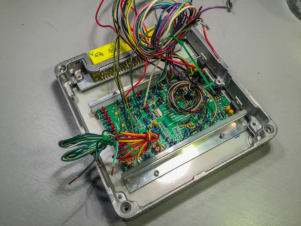
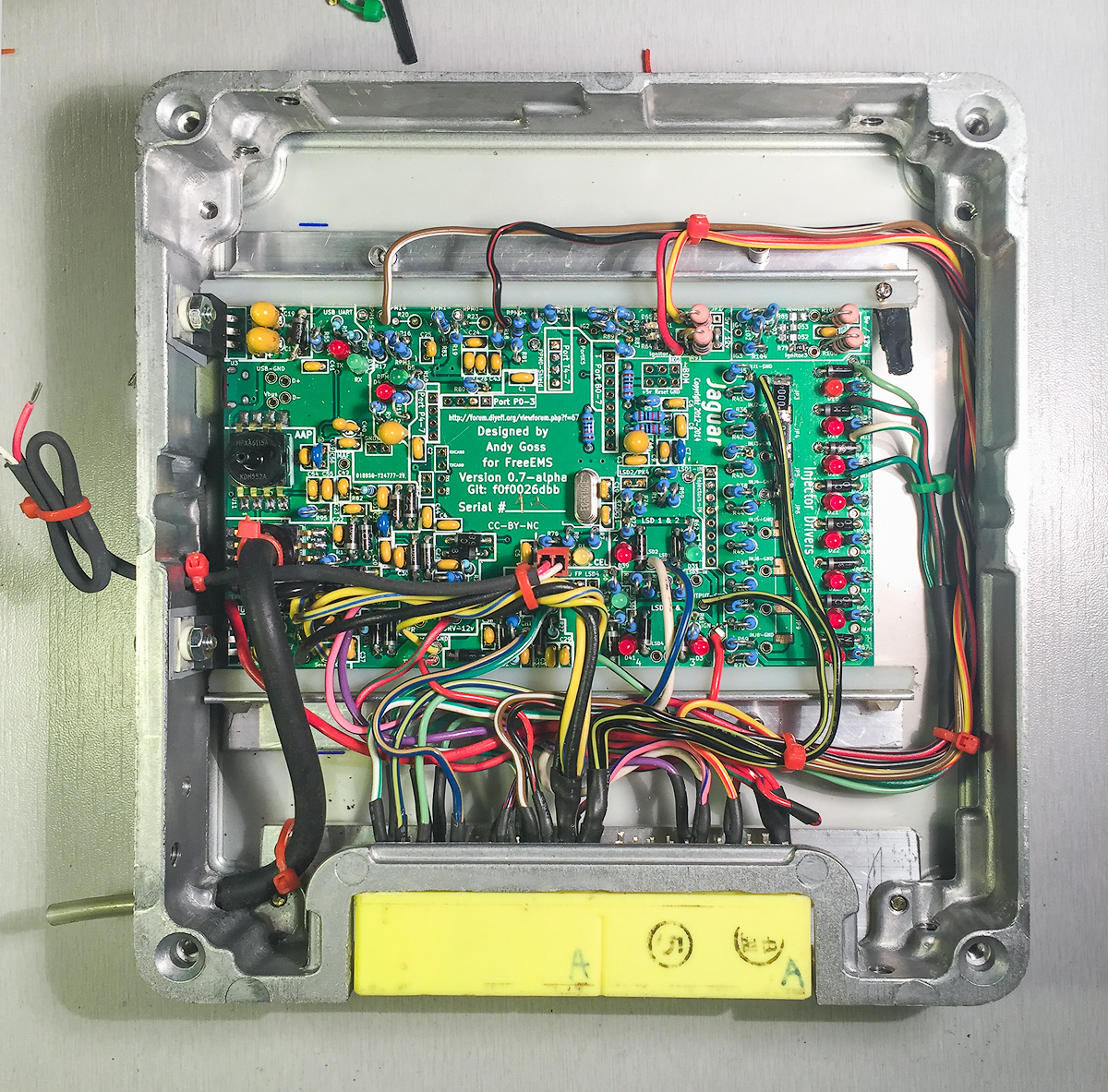
Wife approves: "That picture is lovely, I mean, as far as a circuit picture can go." :-D
I was showing her because I'm impressed. Super neat job, Rob! :-)
A few mostly nit picking questions/comments:
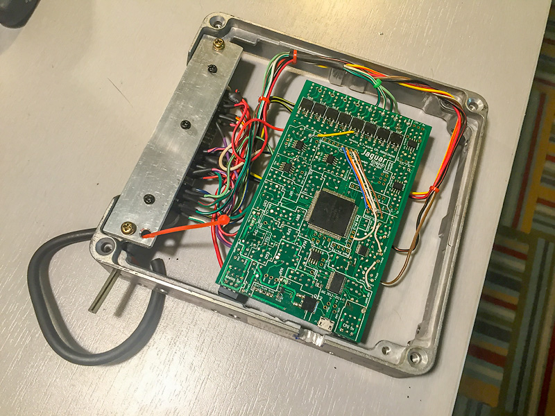
- How stiff is the back panel that the board is, on relative to the frame? Just thinking about those vreg leads again, and vibrations/impacts.
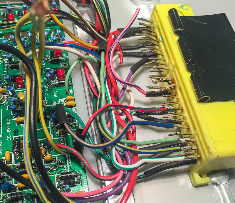
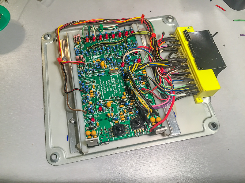
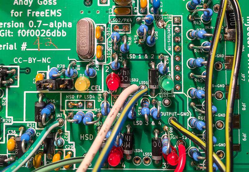
- The three FET ground wires appear to converge on one connector pin? If so you may as well have just run one wire to that pin from the bridged area.
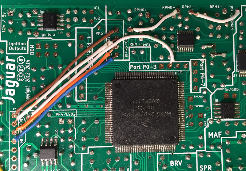
- Ditto the CPU grounds etc, seems to be a bundle of them. The point of more than one is duplication through the connector and loom, mostly. If not there, then no point inside the box.
- If I'd known your plan for orientation I'd have suggested the other 4 injector FETS which would have shortened both the ground wires and inj out wires, but made for longer jumpers on the board.
- Good job on cable tie stopper on load/run wire, and the one on the MAP sensor, too.
- The MAP fitting, is that a metal tube? How did you secure it into the case? Just curious.
- Random idea: Print a copy of your wire colour/Jaguar/OEM pin mapping spreadsheet and glue it on the inside of the top cover :-)
Fingers crossed that the ground scheme is compatible with the loom! Rework would be a challenge :-)