Building the Brains for a Budget Racer: Jaguar A7 #42
Posted: Fri Jul 08, 2016 5:55 pm
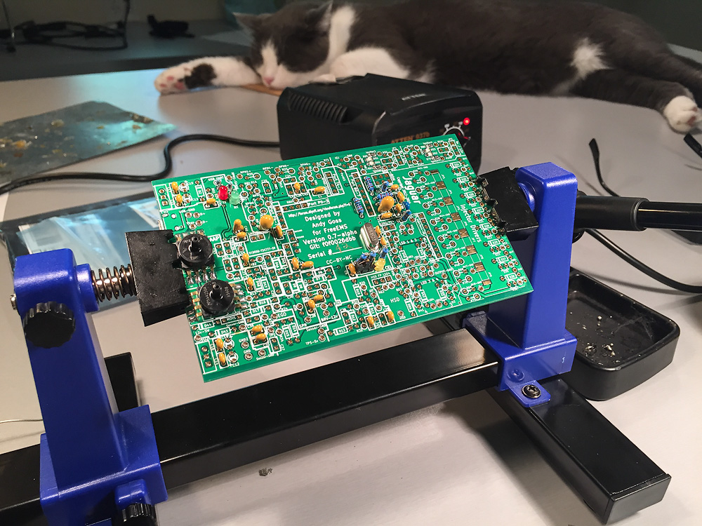
Jagaur A7 #42 is in the works. If all goes well, it will be the brains for a 2016 Grassroots Motorsports Challenge entry.
TRUE DIY engine management discussion forum
http://forum.diyefi.org/
Hmmm, a few things here don't look quite right.m2cupcar wrote:POWER
- 12v-SW - 1C violet - (hot while cranking - ECU power)
- BRV-12v - 1A blue/red - (HOT always)
(note: 1B is Main Relay 12v: FP, injectors, data connector @ fender, EGR solenoids vacuum/vent, purge, IAC, pressure regulator control solenoid valve @ front of engine)
GROUNDS
- GND - 2A to engine block
- GND2 - 2B to engine block
- Sensor-GND - 2D (OE ground circuit for sensors: O2, MAF, CHT, EGR, TPS)
(note: 2C to engine block but connects after joint connector X-35, 1K black/lightgreen to trans & ground joint connector X-35, 2F black/red (changes to black/green) to MAF & ground joint connector X-35)
Should RPM- be RPM1+ ?m2cupcar wrote:RPM Hall/Opto
- configure: connect RPM0- and RPM1- to RPM0 RPM1 Shields
- R16, 17, 18, 19 = 1K 1/4w resistors
- R22, 83, 21, 84 = 1k 1/4w resistors
- R20, 23 = no resistors
- RPM0+ (crank) - 2E White CAS
- RPM- (cam) - 2G Yellow/Blue CAS
99.9% sure the ignition should be jumpered to 12V for these. They're darlington ignitors like most older stuff, right? Not LS1 coils or some such? If they are darlington, and you use 5V, it may run (like my ute), but it'll NEVER be right and never give a good strong spark.m2cupcar wrote:IGNITION (wasted)
- IG1 - 1G brown/yellow (cyl 1/4)
- IG2 - 1H brown (cal 3/4)
- JP1 - 5v
See above, but probably 2A/2B for two of the INJ-GND pins, and a link to the LSD ground from a third hole.m2cupcar wrote:Still trying to figure out the injector setup on the A7 and connections to the Miata harness/injectors.
FUEL INJECTORS
- Install 0ohm jumpers at JP3 JP4 & JP5
- INJ1 - 2Y green/white
- INJ2 - 2Z green
- INJ3 - 2U yellow
- INJ4 - 2V yellow/blue
(This is based on how the A3 injector connections were at P26, 27, 28, 29
What do I do for INJ1-GND, INJ2-GND, INJ3-GND, INJ4-GND?
And Injectors-IN?
This is the fused side of where the positive cable from the battery arrives in the engine bay in the main fuse box.1) BRV (Battery Reference Voltage) will be ever so slight of a battery drain over time - not a huge deal, but something to consider
I found it- IGN-12v @ LSD 3 & 4.3) There is another third 12V input for the ignition drivers, HSD, and LEDs that you need to hook up and haven't listed.
No- all the power grounds are separate. This ground reference for the sensors. EGR is a position sensor, not solenoid.5) O2 and EGR grounds have heater/solenoid current dumped through them?
There are plenty of “free” pins/leads to use as solitary grounds for the injectors and other junk.
- Your PCB needs a solid reference ground, quite possibly the combination of 2C 1K 2F could provide this? Not sure. 2A/2B look highly attractive, but I don't see high current return paths available for the injectors and other junk if you use those for your CPU grounds.
Got it.
- Your solenoids (injectors, idle, etc) need ground return paths of a decent quality to function correctly, so I suspect 2A/2B are these. If I'm right, run these to two of the holes in your block of four injector grounds, and run a bridge from that same block to the LSD ground pin so they all share those two wires.
Agreed.
- Your sensors, all of them, require a good clean ground reference at/through the ECU to avoid voltage drops in any line causing bad readings.
So 2D is right, I think.
Yes!Should RPM- be RPM1+ ?
Every reference I found was 5v- the coils changed in 94, and the ignitor is now part of the coil internally. I’ll do some research to verify.99.9% sure the ignition should be jumpered to 12V for these. They're darlington ignitors like most older stuff, right? Not LS1 coils or some such? If they are darlington, and you use 5V, it may run (like my ute), but it'll NEVER be right and never give a good strong spark.
Tremendously- much appreciated....probably 2A/2B for two of the INJ-GND pins, and a link to the LSD ground from a third hole.
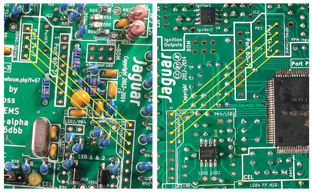
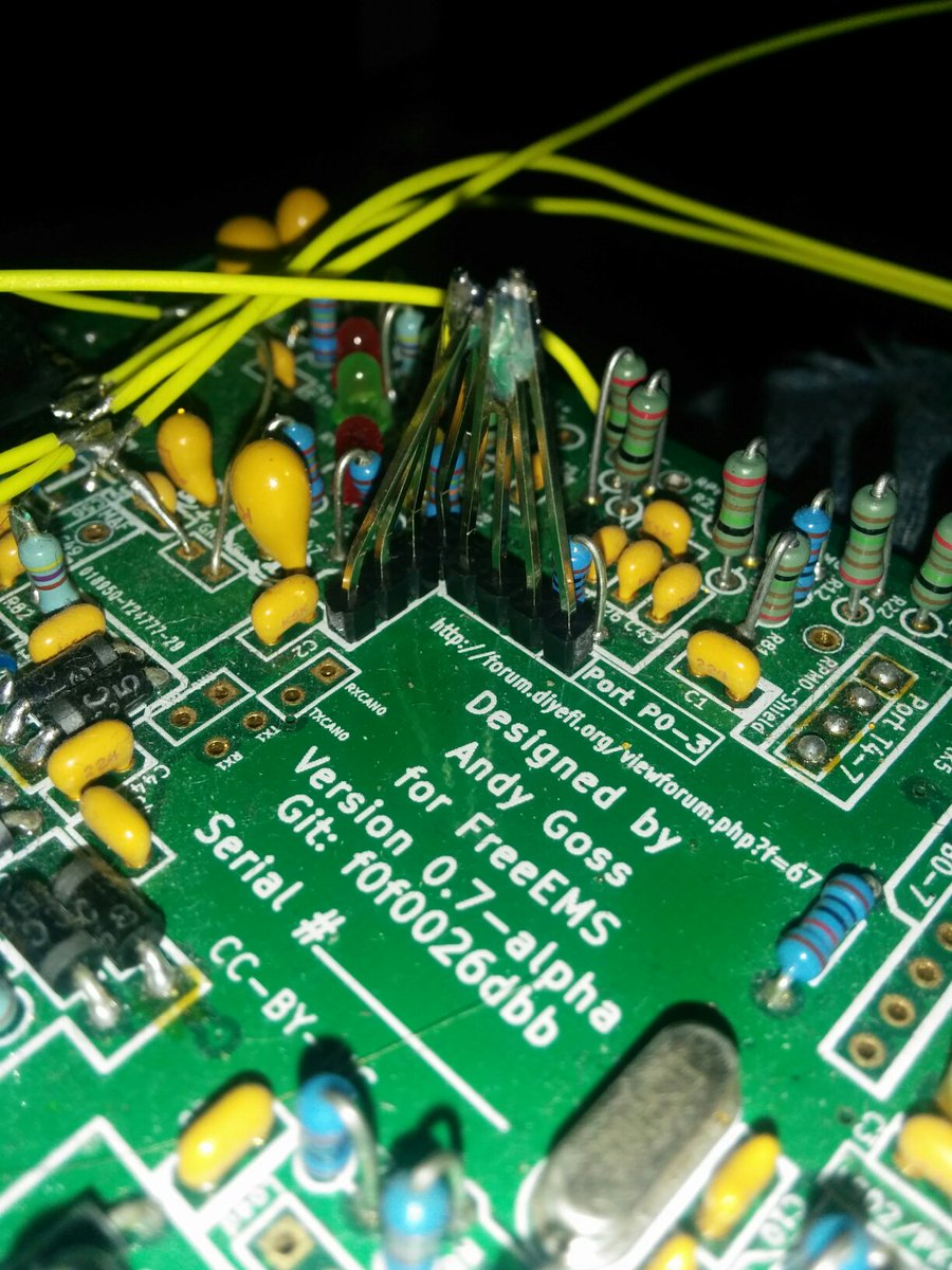
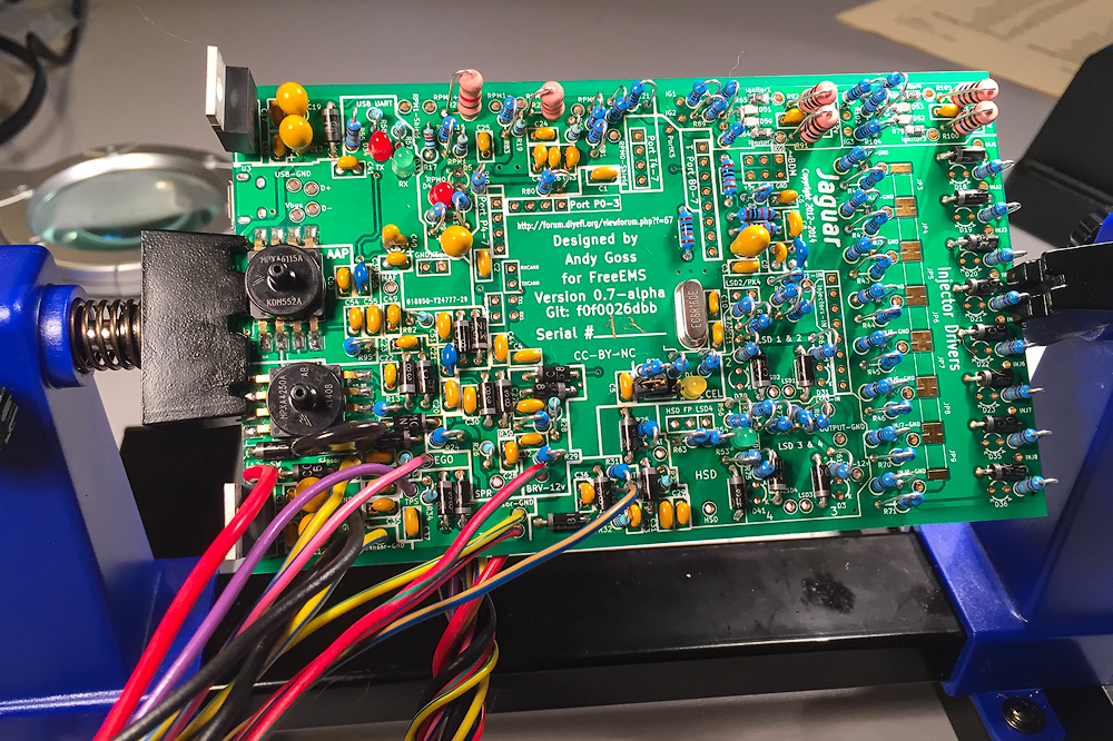
The inputs need to be jumpered to CPU pins. There are four PORT T pins near the CPU, not far from the inputs, run four small reliable wires from those to these.
Hope that all helps!
Like this?The inputs need to be jumpered to CPU pins. There are four PORT T pins near the CPU, not far from the inputs, run four small reliable wires from those to these.