Hey, look, i built something! Neds MicroEMS

All home-built FreeEMS implementations without a forum of their own, usually TA-based.
Ned
TO220 - Visibile
Posts: 11
Joined: Mon May 30, 2011 5:59 am

Hey, look, i built something! Neds MicroEMS

Post by Ned »

Hey guys,

I dont post much here, but pretty close friends with young frederick in real life. He's been complaining that more people need to run his code in their cars, and i kept telling him i would if it was cheaper/easier than the competition ;)

I only have a little 4 cyl car (84 KP Starlet with 7K, soon to be EFI) so i dont need 17 gazillion outputs and inputs to run 15 injectors per port and quadruple spark per valve and what not.

A few friends of mine have all run a microsquirt in their cars very successfully, and i like their little units! Fred will likely disagree, but they are quite cool. If you look at it in a simplistic/binary way of "does it work, yes or no" the the answer is definitely a yes. is it cheap? yes. well, thats all i need from an ECU to some a rubbish inefficient motor designed in the 60's :) but guess what... the dollar tanked, and everything because 50% more expensive of us kiwis, and i spent 6 weeks in the middle of nowhere, with not much to do but watch TV or work on the computer, so i thought "how hard can it be!?" and thats how MicroEMS was born :)

The name is a bit of a cross over between MicroSquirt, and FreeEMS, because it is actually pin compatible with microsquirt... this is done for 2 reasons,
1) if my hardware, or freds software sucks, i can just buy a microsquirt and plug it into the loom and bobs your uncle ;)
2) if would be easier to convince people who already have a microsquirt, or are in the same position as me, to try this FreeEMS thing

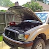
Guess i better show you all a picture aye?
Image

and here's the real one
Image

and one populated.
Image

it even has lights that come on, and the computer actually recognised the USB chip :D which is as far as i've tested it, but pretty happy so far!
Image
Image

It tried to make it software compatible with the jaguar board, so it should all just run with little/no changes,m but i did add a couple things to the board. Most Fred hates, and i wouldnt normally put on the board, but it was to make it pin compatible with microsquirt, so i just went ahead and put it all on anyway :)

Here is the schematic, if you wanna have a look. Pages arent in any sensible order, sorry.

-the analogue inputs are all much the same. I opted for a 2 in 1 diode pack though thats not QUITE as good, but still plenty good enough, i'm sure. Other thing is that the 3rd spare input can be used to measure the battery voltage as a separate input, so you can connect that directly to the battery, or directly to the injector feed, or whatever 12V you want to measure accurately.
-I removed the USB isolation... some people will go "WTF NED!" but i dont have a need for it to be isolated. I really wanted to be able to power the board from USB for when its out of the car and on the bench for whatever reason, and having that isolated is a pain in the back-side, so its no longer isolated, but the 5V from the USB can power the board. (more on that later)
-it has RS232. Why? because microsquirt has it. Will it ever be used? doubt it... but when you're making something to be pin compatible, you cant pick and choose really... The data lines go through a gate, so you can only use one or the other. If they are both talking at the same time, you're going to get garbage on the micro input. It wont break anything electrically though, it just wont work right.
-Also has CAN on board. No idea if freeems even has CAN woring yet, but its hooked up to the pins marked as "we'll use these for CAN one day..." so that should be fine.
-It uses the TC442? fet driver for the ignition. I've had much luck with these before, and fred uses them also so that was a nice coincident :) schematic has a 428 on it to show you can get them as inverted and non-inverted and you can pick what part to actually fit.
-LSD and Injector drives is nothing new, all much the same as other boards.
-power is also much the same, but instead of the dual supplies, i opted for just one.
-Also decided not to fit any tans or electros on the board, and fit only ceramics... i just have a strong dislike for tants and electros and im convinced the ceramics will perform just fine in this application.
- on the reg output, there is an ideal diode. This will allow the board to be powered from USB 5V when there is no regulated 5V present, and not back-feed into the reg. Theres a 0R link there is you dont wanna place the expensive ideal diode though.
-Theres a PI-Filter to filter the analogue reference 5V instead of a whole separate supply and that 5V clamp the jaguar uses. It has its limitations, but i fell its sufficient.
-grounding talk... thats always something that gets people up in arms! so i'm not gonna say anything, but theres an optional 0R is foy wanna link PGND and SGND inside the unit, and if you dont then you can do whatever you like externally. Everything runs on SGND except the LSD and injectors. It's a standard 0805 pad, so maybe a cap would be a good thing to place there instead...
i tried to do a fancy thing with the power LED, and it doesnt quite work and might just need a little resistor change adjustment, but the idea was that the green LED would light up when powered on, but if the fuse blew, it would turn to red. In reality, on USB 5V it goes green, regulated 5V it goes to green and a little red (orange) and fuse blown it goes to red. Close enough :)
- Theres a tacho output, that i attached to some random pin. Hopefully fred can make it do what it needs to do, if not then i dont really mind too much, but i added it anyway.
- theres some optional input protection stuff there for when you dont want to run the MAX9926 and save a couple dollars and sun the inputs directly into the micro.
-theres a silly opto input, just for pin compatibility again
-MAX9926 is much the same, no real changes there either.

thats my quick run through the board. Let me know what you think. I'm obviously too deep into it to make any changes to the schematic etc, but happy to hear your thoughts anyway.

This board, at this stage, is not open hardware. It's my own design and i'm keeping it that way for the time being. happy to share the schematic obviously, and it could likely change to open in the future, but for now i'm holding onto the HW design.
User avatar
Nige
QFP80 - Contributor
Posts: 61
Joined: Sat Aug 10, 2013 5:47 am
Location: New Zealand
Contact:

Re: Hey, look, i built something! Neds MicroEMS

Post by Nige »

I like it, for all of the reasons you already mentioned :)
IRC nick: ignitionigel or Nige
User avatar
Fred
Moderator
Posts: 15431
Joined: Tue Jan 15, 2008 2:31 pm
Location: Home sweet home!
Contact:

Re: Hey, look, i built something! Neds MicroEMS

Post by Fred »

OMG Ned, you told everyone! :-D

What I didn't yet mention in your other thread, but will at some point, is that shiny fancy looking hardware is like tinfoil to a dumb magpie, it attracts the wrong kind of attention. Anyone that's used FreeEMS knows how badly all of the required software sucks, and that's the biggest limitation by far. Attracting silly people to a system that's hard to use in general is a recipe for disappointed people with bad impressions. Hence trying to keep the hardware situation looking iffy for as long as possible while we try to sort out the software side of things. Anyway, aside from that, I love it for quite a few reasons, even if it's got some warts from the short dev cycle and lack of significant detailed feedback/peer review.

Relevant points:

Tacho functionality has some limitations, however is very configurable on most setups. If you need to drive an OS tach, you will also need to convert the signal into voltage spikes. Not hard to do.

Fancy power LED idea is nice. I hope you can refine it for us :-) But wait, what fuse? :-/

Re FET driver for ignition, you should probably spec the part that 95% of people will want to use, like on the Jaguar. Otherwise 90% of people will get the wrong part and suffer.

ESR is the only concern re modern ceramic caps. They're an excellent option if specced correctly.

Not sure I agree with coupling a noisy rail to a clean rail with a cap, but if it was small enough it wouldn't do much harm, I guess.

Not sure about topology or connectivity in general, but I'm sure we'll suss it out together pretty soon :-D

Good to see you posting for the fifth time ever! :-D

Fred.
DIYEFI.org - where Open Source means Open Source, and Free means Freedom
FreeEMS.org - the open source engine management system
FreeEMS dev diary and its comments thread and my turbo truck!
n00bs, do NOT PM or email tech questions! Use the forum!
The ever growing list of FreeEMS success stories!
User avatar
ruzki
QFP80 - Contributor
Posts: 86
Joined: Thu Jun 20, 2013 4:24 pm

Re: Hey, look, i built something! Neds MicroEMS

Post by ruzki »

Attracting silly people to a system that's hard to use in general is a recipe for disappointed people with bad impressions.
... yep here i am ! :lol2:

Ned: Do you want to make the rest of the project public ?

Georg
User avatar
ToxicGumbo
LQFP144 - On Top Of The Game
Posts: 474
Joined: Tue Jan 03, 2012 8:37 pm
Location: Manhattan, KS. USA

Re: Hey, look, i built something! Neds MicroEMS

Post by ToxicGumbo »

+1 on public. I'm really in awe of this sleeper project that appeared out of nowhere and nearly pooped myself when I opened the thread yesterday. I hope you can beef up the aspects you feel are a little less than ideal, but overall it looks really polished and well thought out.


-Jeff
Ned
TO220 - Visibile
Posts: 11
Joined: Mon May 30, 2011 5:59 am

Re: Hey, look, i built something! Neds MicroEMS

Post by Ned »

Not bad aye Fred when post 5 is of a built ECU ;)

and fuse wise, thers a polyfuse on the board (actually, theres 2)

And i'll likely make this public, but not until i've actually had it running in the car and tested all/most the functionality of it all and found what does/doesnt work. I would hate for you guys to go "ooh, fancy! i want!" and spend $300 on something with a big fundamental flaw in it.

I made 10 PCBs and they are/have been distributed to a few local people with a good knowledge of FreeEMS and are driven to using and testing the hardware. I need my car running on it by 12th dec at the latest, so there is strong motivation by me to get it going and find the short comings and fuck ups asap!

Thanks for all the kind words :)
User avatar
Fred
Moderator
Posts: 15431
Joined: Tue Jan 15, 2008 2:31 pm
Location: Home sweet home!
Contact:

Re: Hey, look, i built something! Neds MicroEMS

Post by Fred »

LOL, yeah, you keep telling yourself that ;-) What amazes me is that you didn't use the available schematics at all, and designed all the parts and 3D models from scratch, all within 2 weeks. I admire your talent with CAD software, and once I educate you in the ways of engine control, you'll be formidable :-D

Explain the fuses to me when we next convene.

Ruzki, you built your own shiny hardware, like Ned, I can't really stop that, lol.

Guys, re "make it open, make it open", I know you meant no harm, but closed hardware is OK, and we should respect his decision to do whatever the f*** he wants. There will be benefits and draw backs to both open and closed designs for both creator and user. Things will even out in the end.

Fred.
DIYEFI.org - where Open Source means Open Source, and Free means Freedom
FreeEMS.org - the open source engine management system
FreeEMS dev diary and its comments thread and my turbo truck!
n00bs, do NOT PM or email tech questions! Use the forum!
The ever growing list of FreeEMS success stories!
User avatar
Hentai
LQFP144 - On Top Of The Game
Posts: 302
Joined: Sun Jul 18, 2010 2:35 pm

Re: Hey, look, i built something! Neds MicroEMS

Post by Hentai »

I might be interested in one depending on cost for a 240sx that already shares the same connector running an electromotive tec gt.
User avatar
sim
LQFP112 - Up with the play
Posts: 112
Joined: Thu Jun 02, 2011 8:17 pm

Re: Hey, look, i built something! Neds MicroEMS

Post by sim »

Oooh, shiny tinfoil!

Nice work Ned!
<@TekniQue> but in the end, it's code that makes a computer useful
User avatar
ruzki
QFP80 - Contributor
Posts: 86
Joined: Thu Jun 20, 2013 4:24 pm

Re: Hey, look, i built something! Neds MicroEMS

Post by ruzki »

Ned !
You may could tell us some more about the PCB design ?
I personally would like to know how such dense PCB design is done ? How many Layer´s did you use ?
How does your mixed signal grounding looks like ?
Guys, re "make it open, make it open", I know you meant no harm, but closed hardware is OK, and we should respect his decision to do whatever the f*** he wants. There will be benefits and draw backs to both open and closed designs for both creator and user. Things will even out in the end.
I totally respect the decision to make the design closed .. but people have to reckon with such questions in a forum that has the letters "diy" in it :D
Post Reply