My 87 toyota supra hardware build
Posted: Wed Dec 25, 2013 7:25 am
Hi all.
I've got a 1987 Toyota Supra turbo that I have put way too much of my life into, so I figured why not put more.

Its got the 7mgte inline 6. I've been pretty happy with 300rwhp for a while, and have fiddled with trying to make my own piggyback fuel controller using an fpga loaded with openrisc and some custom HDL on it, but decided going standalone is the right path forward. For the last few weeks I've been researching freeems and getting the basic fundamentals down.
I've got most of it planned out and have started the build, but figured before I go too much further I should run everything up here to make sure I'm not doing something really dumb.
The engine semisequential injection (3 batches of two injectors), and wasted spark (also 3 batches of two). Firing order is 1-5-3-6-2-4.
It uses a toyota CPS with three VR outputs. NE with 24 pulses per cam rotation, and G1/G2 each triggering once per rotation. I've decided that I can use NE/G1 with a 24/1 decoder (eventeeth) that already exists. The stock engine uses a KVAFM which I fully intend to replace with speed-density using a MAP sensor and an IAT after the intercooler. Exact placement of these is not yet decided. I plan to use the existing coolant temperature sensor after calibrating it. The injectors I've got installed at the moment are some Bosch 550cc low impedence injectors that are run through a giant resistor for the ecu to drive. I've toyed with the idea of using a low-z driver, but figured for the time being I'll continue using the stock resistor pack until I need replacement injectors and then I can just get some high-z ones.
I decided I would be most comfortable doing the hardware piece by piece on perfboard and soldering rather than trying to make my own pcb. I have very little experience with pcb design, and only marginal
experience with soldering. I've done some SMT, but prefer through-hole components, and even then I'd say my soldering is not particularly high quality. I purchased a TA board and a Jimstim. I started out by going through the Ravage and Jaguar schematics to choose parts, basing various subcircuits off of those designs. Injector/Ignition drivers, analog inputs, and most of the power supplies are shamelessly copied from Ravage. I assembled a list of parts from those designs, substituted through-hole components where appropriate, and then bought a lot of them:
https://pastee.org/2tur7
Before getting the hardware started, I wanted to make sure I could get all the software components working well. I was able to compile freeems-loader with zero problems on OpenBSD. Emsstudio took a bit
more effort, as that code depends on a relatively recent version of qwt. Making it work with older qwt's just involved a very simple change (the use of the graph set_samples calls), and now emsstudio works great and can talk to the board. Rather than try to get all the toolchain set up I took the easy route and set up a debian VM and installed the tools necessary to build. I will say, that part was extremely easy, thanks to anyone who made it so simple and easy to configure/build.
I started off with the power supply, using two 5V regulators just like in Ravage. One thing I'm not 100% clear on is the use of a mcu pin to turn on/off the accessory 5V supply. There seems to be some debate about if this is a good idea, perhaps I should just switch it on key, as right now it seems that there is no freeems support for always on (is this true?). Primary 5V supplies the TA board (bypassing the onboard regulator), and the other powers the analog sensors, jimstim, and anything else I come across that wants 5V. I've separated each ground, although in my pictures below they all connect to the same point for testing.
I went the simple route on the VR board and just outright bought and assembled one. It uses the LM1815 ICs, and I have not tested it with my actual CPS yet.
I just finished the ignition drivers a few days ago, and it feels pretty great to be able to adjust the jimstim tach output and watch lights blink in sequence.
The stock 7mgte uses a igniter that operates in multiplex; There is one distributor-like output and two other control wires that designate which set to fire. This could probably be made to work with FreeEMS, but in the supra community the igniter is considered problematic, so I invested in a 3 channel igniter from the later Lexus models (DH61). I imagine it'll be simple to integrate with FreeEMS. It apparently automatically controls dwell, I'll probably need some guidance on setting that up.
I've added in #ifdef'd sections into my local checkout of freeems-vanilla that I'll put up on my own github in the near future, but right now there's not much different. I set the engine sizes/injector sizing, and added a section for my event control.
#elif CONFIG == SUPRA_ID // Firing order 1-5-3-6-2-4
anglesOfTDC: {ANGLE(0), ANGLE(120), ANGLE(240), ANGLE(360), ANGLE(480), ANGLE(600), ANGLE(0), ANGLE(120), ANGLE(240), ANGLE(360), ANGLE(480), ANGLE(600)},
outputEventPinNumbers: {3,4,5,3,4,5,0,1,2,0,1,2}, // An example of wiring your engine with cylinder one on output one, harder to grok
schedulingConfigurationBits: {1,1,1,1,1,1,0,0,0,0,0,0}, // Ones represent scheduling for injection, zeros represent scheduling for ignition
decoderEngineOffset: ANGLE(0.00), // Trim fuel injection END point with this value.
numberOfConfiguredOutputEvents: 12, // 6 coil events, 6 injection events
numberOfInjectionsPerEngineCycle: 2 // Semi-sequential
I'm pretty confident I have this close to right at least for the ignition sequencing, but I'm still a little unclear on what I'm doing. I figured I'd wire up the igniter driver ports to PT0-2 and the injector drivers to PT3-5. However, while my ignition order makes sense to me ( firing order 153624, wasted spark pairs are 1-6 2-5 3-4), the fuel injector order makes very little sense and I'm not sure how
to set it up. They are wired in 1-4 2-6 3-5 pairs, and I assume they're fired in that sequence too. I'll be honest and say that the timing of these things is still something I'm starting to understand.
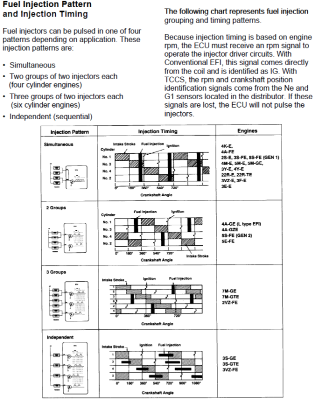
Nor do I fully understand how the timing of the injection batches is supposed to be done. About all I have to go on is this random picture on the internet:
Current collection of pictures of the hardware: http://imgur.com/a/iJOzZ
A lot of its hacky, and I'll probably end up redoing parts of it.
I know thats all kind of a lot to post, but I did want to have a pretty good idea of what I was doing and get started before getting on here. Even then I'm certain I've missed some things.
Thank you and Merry Christmas.
I've got a 1987 Toyota Supra turbo that I have put way too much of my life into, so I figured why not put more.
Its got the 7mgte inline 6. I've been pretty happy with 300rwhp for a while, and have fiddled with trying to make my own piggyback fuel controller using an fpga loaded with openrisc and some custom HDL on it, but decided going standalone is the right path forward. For the last few weeks I've been researching freeems and getting the basic fundamentals down.
I've got most of it planned out and have started the build, but figured before I go too much further I should run everything up here to make sure I'm not doing something really dumb.
The engine semisequential injection (3 batches of two injectors), and wasted spark (also 3 batches of two). Firing order is 1-5-3-6-2-4.
It uses a toyota CPS with three VR outputs. NE with 24 pulses per cam rotation, and G1/G2 each triggering once per rotation. I've decided that I can use NE/G1 with a 24/1 decoder (eventeeth) that already exists. The stock engine uses a KVAFM which I fully intend to replace with speed-density using a MAP sensor and an IAT after the intercooler. Exact placement of these is not yet decided. I plan to use the existing coolant temperature sensor after calibrating it. The injectors I've got installed at the moment are some Bosch 550cc low impedence injectors that are run through a giant resistor for the ecu to drive. I've toyed with the idea of using a low-z driver, but figured for the time being I'll continue using the stock resistor pack until I need replacement injectors and then I can just get some high-z ones.
I decided I would be most comfortable doing the hardware piece by piece on perfboard and soldering rather than trying to make my own pcb. I have very little experience with pcb design, and only marginal
experience with soldering. I've done some SMT, but prefer through-hole components, and even then I'd say my soldering is not particularly high quality. I purchased a TA board and a Jimstim. I started out by going through the Ravage and Jaguar schematics to choose parts, basing various subcircuits off of those designs. Injector/Ignition drivers, analog inputs, and most of the power supplies are shamelessly copied from Ravage. I assembled a list of parts from those designs, substituted through-hole components where appropriate, and then bought a lot of them:
https://pastee.org/2tur7
Before getting the hardware started, I wanted to make sure I could get all the software components working well. I was able to compile freeems-loader with zero problems on OpenBSD. Emsstudio took a bit
more effort, as that code depends on a relatively recent version of qwt. Making it work with older qwt's just involved a very simple change (the use of the graph set_samples calls), and now emsstudio works great and can talk to the board. Rather than try to get all the toolchain set up I took the easy route and set up a debian VM and installed the tools necessary to build. I will say, that part was extremely easy, thanks to anyone who made it so simple and easy to configure/build.
I started off with the power supply, using two 5V regulators just like in Ravage. One thing I'm not 100% clear on is the use of a mcu pin to turn on/off the accessory 5V supply. There seems to be some debate about if this is a good idea, perhaps I should just switch it on key, as right now it seems that there is no freeems support for always on (is this true?). Primary 5V supplies the TA board (bypassing the onboard regulator), and the other powers the analog sensors, jimstim, and anything else I come across that wants 5V. I've separated each ground, although in my pictures below they all connect to the same point for testing.
I went the simple route on the VR board and just outright bought and assembled one. It uses the LM1815 ICs, and I have not tested it with my actual CPS yet.
I just finished the ignition drivers a few days ago, and it feels pretty great to be able to adjust the jimstim tach output and watch lights blink in sequence.
The stock 7mgte uses a igniter that operates in multiplex; There is one distributor-like output and two other control wires that designate which set to fire. This could probably be made to work with FreeEMS, but in the supra community the igniter is considered problematic, so I invested in a 3 channel igniter from the later Lexus models (DH61). I imagine it'll be simple to integrate with FreeEMS. It apparently automatically controls dwell, I'll probably need some guidance on setting that up.
I've added in #ifdef'd sections into my local checkout of freeems-vanilla that I'll put up on my own github in the near future, but right now there's not much different. I set the engine sizes/injector sizing, and added a section for my event control.
#elif CONFIG == SUPRA_ID // Firing order 1-5-3-6-2-4
anglesOfTDC: {ANGLE(0), ANGLE(120), ANGLE(240), ANGLE(360), ANGLE(480), ANGLE(600), ANGLE(0), ANGLE(120), ANGLE(240), ANGLE(360), ANGLE(480), ANGLE(600)},
outputEventPinNumbers: {3,4,5,3,4,5,0,1,2,0,1,2}, // An example of wiring your engine with cylinder one on output one, harder to grok
schedulingConfigurationBits: {1,1,1,1,1,1,0,0,0,0,0,0}, // Ones represent scheduling for injection, zeros represent scheduling for ignition
decoderEngineOffset: ANGLE(0.00), // Trim fuel injection END point with this value.
numberOfConfiguredOutputEvents: 12, // 6 coil events, 6 injection events
numberOfInjectionsPerEngineCycle: 2 // Semi-sequential
I'm pretty confident I have this close to right at least for the ignition sequencing, but I'm still a little unclear on what I'm doing. I figured I'd wire up the igniter driver ports to PT0-2 and the injector drivers to PT3-5. However, while my ignition order makes sense to me ( firing order 153624, wasted spark pairs are 1-6 2-5 3-4), the fuel injector order makes very little sense and I'm not sure how
to set it up. They are wired in 1-4 2-6 3-5 pairs, and I assume they're fired in that sequence too. I'll be honest and say that the timing of these things is still something I'm starting to understand.
Nor do I fully understand how the timing of the injection batches is supposed to be done. About all I have to go on is this random picture on the internet:
Current collection of pictures of the hardware: http://imgur.com/a/iJOzZ
A lot of its hacky, and I'll probably end up redoing parts of it.
I know thats all kind of a lot to post, but I did want to have a pretty good idea of what I was doing and get started before getting on here. Even then I'm certain I've missed some things.
Thank you and Merry Christmas.