The Hotel is currently running the original TA board, built up by Fred, modified by Dan and now hacked my hands.
I felt it was time today to get the TA board into an enclosure for a number of reasons
- Stop unwanted interference, a prime example of this is the log of it receiving text messages

- Passengers need somewhere to place their feet, and a general tidy up of wires doesn't go astray
- The WOF is well overdue, and it's not a good look ems floating around. An being a daily driver I really don't want it to fail.
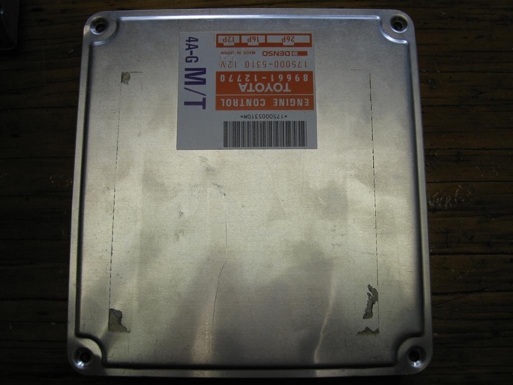
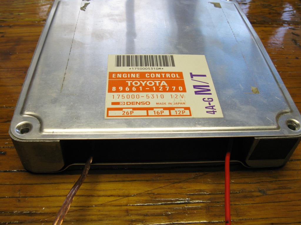
In the name of FreeEMS I located my 4AGE ems and decided to use this as the enclosure (the 4age will be Ravage, an can never go back).
The enclosure is fantastic for a number of reasons, one size, two full aluminum case, three really easy to work with.
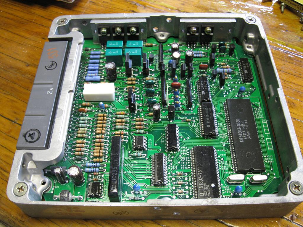
Step one: Dismantle the remove OEM circuit board with connector. Note how the transistors are mounted to their own aluminium pad which is in turn bolted to the enclosure, it makes for easy assembly, an idea for ravage maybe?
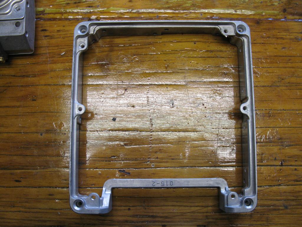
With the enclosure stripped down were left with the surround, as you can see really easy to work with as bare structure is clean and simple.
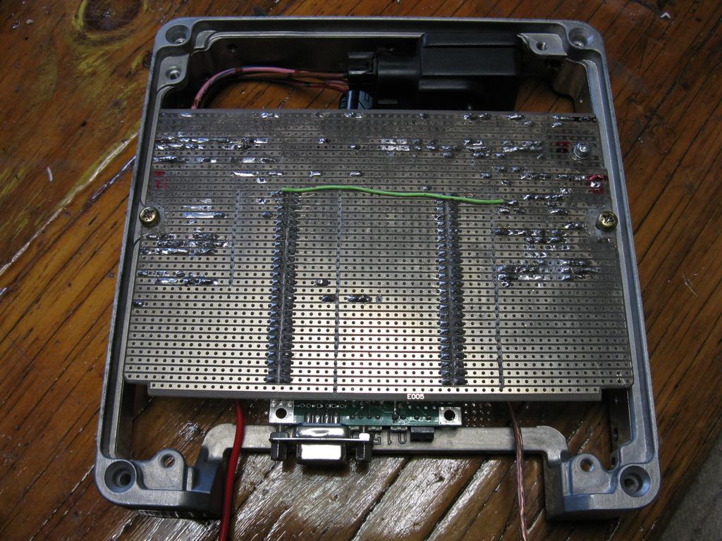
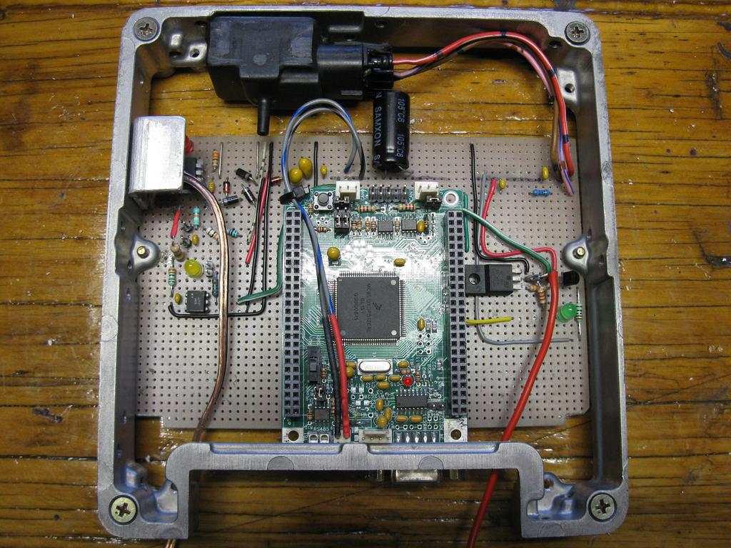
Step two: Mount the board, surprisingly enough the board was snug fit. later I found out that Fred had planned originally to mount it in a 4afe case, now that's uncanny. Yo Fred great minds think alike

So I relocated some components that were close to the mounting area and then removed all copper surrounding screws where I was mounting the board. Two holes were drilled, I made one slotted (the one closest to the heat sink) to allow a little adjustments. It has been mounted in the location seen to minimize penetrations needed while maximise resistance to noise interference.
An aluminium right angle was made for the regulator that could be fastened under the reg and then fastened to the case. Heat paste was placed under each of the two joining surfaces. Note: the reg is isolated from the heat sink as the case will be grounded.
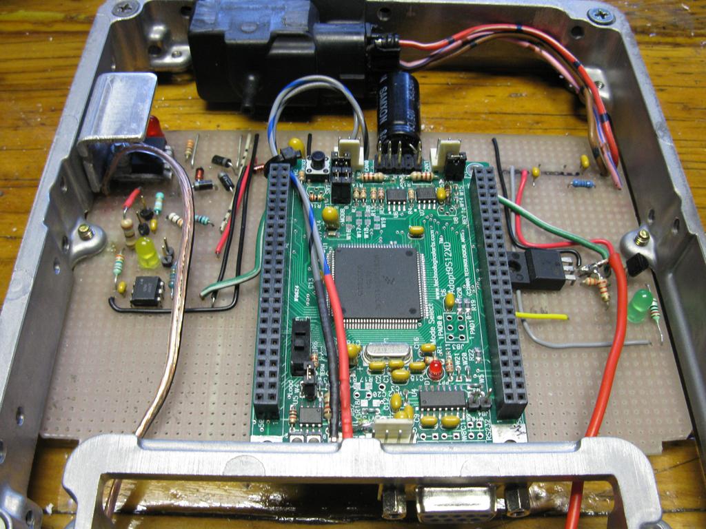
From the top side the reg can be seen at the top left, just below it is the opto input circuit (with yellow led). To the top right is MAP conditioner circuit and below it is the igniter circuit. The big black thing at the top is a Toyota OEM map sensor, and lastly the large cap (black) across the 5v rails. The cap was placed as close as possible to the TA power input so that it has a stable power source.
A close up on the setup. The cable for input to opto is missing and was added after the images were taken.
Wires coded as follows:
- Red = ign
- Clear = +12v and Ground
- Green/Yellow (not seen here) = hall input
Finally the completed enclosure, will be grounded to the firewall in the car. Photo of this to follow in the next post.
Preston.