
Thanks for the comments Fred.
I've sketched up circuits, using the high current driver for the
coils, and an inverting line driver for the CAS input.
The sketch is posted to the main build thread:
viewtopic.php?p=16800#p16800
Hopefully I'm not too far off with this. I should be able to get
this stuff soldered up tomorrow afternoon.
With luck, I'll find time on Sunday or Monday to get out to the
Pick-A-Part to scavenge some MAP sensors. That should have most
of the hardware sorted out, once I build conditioning circuits
for the MAPs.
That's it for tonight,
sim's Volvo 245 comments
Re: sim's Volvo 245 comments
<@TekniQue> but in the end, it's code that makes a computer useful

Re: sim's Volvo 245 comments
OK, my comments:
1) Build all 6 channels of the output line driver the same, 1k from PORT T pin, LED+3k to ground/200ohm from driver to external device
2) use the other channels for the p&h box
3) for which ever you choose to have wasted/semi on, parallel two coils/p&h channels onto one line driver channel
4) You'll get better overall performance if you drive the LS1 coils in pseudo wasted spark and run sequential injection. I recommend this.
5) If you build the 6 channels the same, it's trivial wiring change to go from COP now to Sequential later and you'll HAVE to get your setup correct if you run COP now.
The diagram for the CAS inputs is good. PT0 and PT1 are the pins. PT0 gets the outer slots (4 or 24) and PT1 gets the inner slots (1 or 2), I always forget the naming on the CAS, so you can document that here when you suss it out :-)
PS, I like your pen drawing, it's neat and readable! Well done :-)
Fred.
DIYEFI.org - where Open Source means Open Source, and Free means Freedom
FreeEMS.org - the open source engine management system
FreeEMS dev diary and its comments thread and my turbo truck!
n00bs, do NOT PM or email tech questions! Use the forum!
The ever growing list of FreeEMS success stories!
FreeEMS.org - the open source engine management system
FreeEMS dev diary and its comments thread and my turbo truck!
n00bs, do NOT PM or email tech questions! Use the forum!
The ever growing list of FreeEMS success stories!
Re: sim's Volvo 245 comments
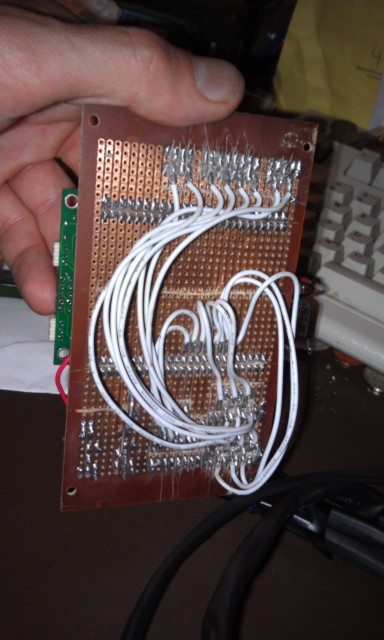
BTW, I just took the img tags off of your full size photos so as not to take excess time loading and auto resizing etc. I left the first one as it's a nice pic and one doesn't hurt :-) If you wanna put some resized variants up in their place and put the tags back, be my guest. Hopefully you're not offended that I messed with your posts...
DIYEFI.org - where Open Source means Open Source, and Free means Freedom
FreeEMS.org - the open source engine management system
FreeEMS dev diary and its comments thread and my turbo truck!
n00bs, do NOT PM or email tech questions! Use the forum!
The ever growing list of FreeEMS success stories!
FreeEMS.org - the open source engine management system
FreeEMS dev diary and its comments thread and my turbo truck!
n00bs, do NOT PM or email tech questions! Use the forum!
The ever growing list of FreeEMS success stories!
Re: sim's Volvo 245 comments
Good advice Fred, I'll use all of the six Port T channels, mightFred wrote:OK, my comments:
1) Build all 6 channels of the output line driver the same, 1k from PORT T pin, LED+3k to ground/200ohm from driver to external device
2) use the other channels for the p&h box
3) for which ever you choose to have wasted/semi on, parallel two coils/p&h channels onto one line driver channel
4) You'll get better overall performance if you drive the LS1 coils in pseudo wasted spark and run sequential injection. I recommend this.
5) If you build the 6 channels the same, it's trivial wiring change to go from COP now to Sequential later and you'll HAVE to get your setup correct if you run COP now.
The diagram for the CAS inputs is good. PT0 and PT1 are the pins. PT0 gets the outer slots (4 or 24) and PT1 gets the inner slots (1 or 2), I always forget the naming on the CAS, so you can document that here when you suss it out
PS, I like your pen drawing, it's neat and readable! Well done
Fred.
as well, there are six drivers on the chip.
I'm initially going to set up for four sequential ignition
channels, but if I get fuel sorted before the xgate code is ready
to test, I'll switch to wasted spark and sequential fuel.
I was wondering what PT0 and PT1 were used for.
I've updated my post with the CAS pins and six drivers, I'm
trying to do a good job of documenting this build.
Oh, and my apologies for not scaling those images, that was
pretty ignorant of me. I've reduced the file sizes by about a
factor of ten, and reinstated the img tags.
<@TekniQue> but in the end, it's code that makes a computer useful
Re: sim's Volvo 245 comments
Awesome on all counts! :-)
Thanks for the description of the CAS stuff, I'll be using your post for a reference in future lol.
Thanks for the description of the CAS stuff, I'll be using your post for a reference in future lol.
DIYEFI.org - where Open Source means Open Source, and Free means Freedom
FreeEMS.org - the open source engine management system
FreeEMS dev diary and its comments thread and my turbo truck!
n00bs, do NOT PM or email tech questions! Use the forum!
The ever growing list of FreeEMS success stories!
FreeEMS.org - the open source engine management system
FreeEMS dev diary and its comments thread and my turbo truck!
n00bs, do NOT PM or email tech questions! Use the forum!
The ever growing list of FreeEMS success stories!
Re: sim's Volvo 245 comments
If it's not cool for this to be in here, let me know and I'll remove it.
Also make sure the LED and its resistor are attached directly to the driver chip along with the ~200 ohm such that they both receive full drive and neither screws up the other.
Hope that helps :-)
Most common garden LEDs have a *max* current of about 20mA. You can run them at lower current with reduced brightness down to some point when they no longer light. You don't have to run them at 20mA and the life is longer the more gently you run them. I'd probably recommend about 2k for the LED and 220 for the series limit to the coil/p&h board/whatever is fine.[06:35] <simis> So, if I use a 3k ohm resistor in series with a LED, at 5v, I get 1mA of power, right? It seems to me like the current limiting resisitor should be more like 300 ohms.
Right, but you wouldn't drive the LED so hard, it only needs to be an indicator, it doesn't need to light the road ahead ;-)[06:40] <simis> Though the line driver can drive about 25mA, so that does not leave much left after driving a LED at a decent current.
Nope, that's wrong. Driving the LED through a 3k () and a DEAD SHORT through a 200 ohm resistor is 26mA while the output is high, only. The 200 is only there for dead short situations. If you're confident your wiring is perfect, skip it and drive the coil directly. (don't really do that, but...) The reality is that the coil will "stretch" the resistor a bit during switching, but while in dwell or out of dwell it will drop virtually no voltage and the current supplied will be virtually zero also, only depending on the input impedance of the coils/p&h box. Does that make more sense?[06:43] <simis> Driving a LED through a 3k ohm resistor, and a LS1 coil through a 200 ohm resistor is 26mA, at 5v, close enough to the spec of the driver, I guess.
Blame the home made booze! :-)[06:43] <simis> But will the LED even light up?
[06:44] <simis> Or am I fucking something up here?
If it lights up fine with 3.3k, use it. Just make sure you can see it during daylight too, not ONLY in the dark of night in the workshop :-)[07:05] <simis> Well, based on sucking one to see, a 3K3 resistor will, in fact, light up a LED at 5v. A little dimmer than the 220R, but not really much.
Also make sure the LED and its resistor are attached directly to the driver chip along with the ~200 ohm such that they both receive full drive and neither screws up the other.
Hope that helps :-)
DIYEFI.org - where Open Source means Open Source, and Free means Freedom
FreeEMS.org - the open source engine management system
FreeEMS dev diary and its comments thread and my turbo truck!
n00bs, do NOT PM or email tech questions! Use the forum!
The ever growing list of FreeEMS success stories!
FreeEMS.org - the open source engine management system
FreeEMS dev diary and its comments thread and my turbo truck!
n00bs, do NOT PM or email tech questions! Use the forum!
The ever growing list of FreeEMS success stories!
Re: sim's Volvo 245 comments
No worries, If I come across as looking a bit foolish on theFred wrote:If it's not cool for this to be in here, let me know and I'll remove it.
internet, it's probably because I'm a fool.
I know (remember) just enough about electronics to be dangerous.
I do try to make sure I understand how things work before wiring
them up, rather than practice cargo cult soldering.
Hopefully, this will result in some half decent documentation as
a side effect.
This makes good sense to me.Fred wrote:Most common garden LEDs have a *max* current of about 20mA. You can run them at lower current with reduced brightness down to some point when they no longer light. You don't have to run them at 20mA and the life is longer the more gently you run them. I'd probably recommend about 2k for the LED and 220 for the series limit to the coil/p&h board/whatever is fine.[06:35] <simis> So, if I use a 3k ohm resistor in series with a LED, at 5v, I get 1mA of power, right? It seems to me like the current limiting resisitor should be more like 300 ohms.
Right, but you wouldn't drive the LED so hard, it only needs to be an indicator, it doesn't need to light the road ahead[06:40] <simis> Though the line driver can drive about 25mA, so that does not leave much left after driving a LED at a decent current.
Yes, your explanation makes sense. 26mA is only a worst caseFred wrote:Nope, that's wrong. Driving the LED through a 3k () and a DEAD SHORT through a 200 ohm resistor is 26mA while the output is high, only. The 200 is only there for dead short situations. If you're confident your wiring is perfect, skip it and drive the coil directly. (don't really do that, but...) The reality is that the coil will "stretch" the resistor a bit during switching, but while in dwell or out of dwell it will drop virtually no voltage and the current supplied will be virtually zero also, only depending on the input impedance of the coils/p&h box. Does that make more sense?[06:43] <simis> Driving a LED through a 3k ohm resistor, and a LS1 coil through a 200 ohm resistor is 26mA, at 5v, close enough to the spec of the driver, I guess.
load.
I was not sure what kind of load the coil ignitor presented,
whether a resistive load, or something like a LED that has
essentially no resistance.
With a 3K3R on the LED, and a 220R on the coil line, the worst
case is actually just over 24mA, just inside the driver spec.
I make strictly high-end booze, and try not to post to IRC afterFred wrote:Blame the home made booze![06:43] <simis> But will the LED even light up?
[06:44] <simis> Or am I fucking something up here?
imbibing too much. When I've had too much to trust my judgment,
I tend to sit around thinking about ways things could go wrong.
Heh, I asked these questions in the IRC channel, and then IFred wrote:If it lights up fine with 3.3k, use it. Just make sure you can see it during daylight too, not ONLY in the dark of night in the workshop[07:05] <simis> Well, based on sucking one to see, a 3K3 resistor will, in fact, light up a LED at 5v. A little dimmer than the 220R, but not really much.
realized that everything I needed to answer the question for
myself was sitting on my desk right in front of me. A couple
minutes later, I knew the LEDs would work fine.
It does indeed, thanks for the feedback Fred.Fred wrote:
Also make sure the LED and its resistor are attached directly to the driver chip along with the ~200 ohm such that they both receive full drive and neither screws up the other.
Hope that helps
<@TekniQue> but in the end, it's code that makes a computer useful

Re: sim's Volvo 245
interesting........ I like it! keep up the good work!
Re: sim's Volvo 245 comments
Awesome! I LOVE how unique everyone's different attempts at TA goodness are :-) :-) :-)sim wrote:At this point, I have a power supply built on veroboard along
with connectors for the TA card, and line drivers for Port T --
two input for the CAS, four output for the coils and two spare.
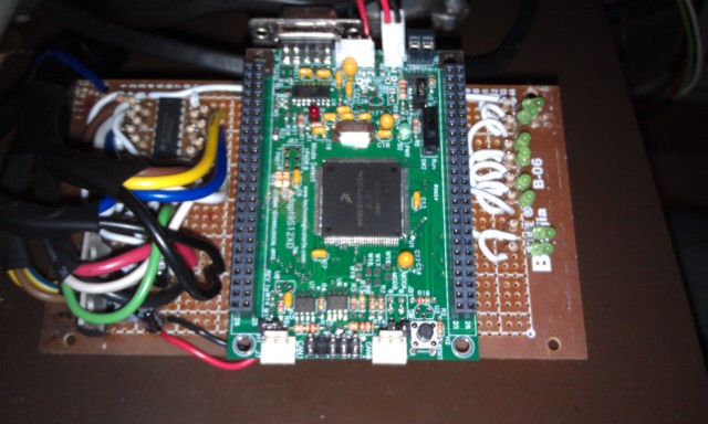
You'll only need a few hundred at most. We'll talk always on later when we start to need it. You could be the first tester :-)I built two identical supplies side by side using LM1940T
regulators and the circuit from their datasheet. One regulator
powers the TA board, the other is powering the Ignition board.
The grounds are tied together and power is fed in through a three
pin connector. Both positive leads are tied together in a mating
connector and wired to an old laptop supply feeding 12.5v at 3A.
I built two supplies thinking that one might be "always on" for
the TA board at some time in the future. In any case, it provides
a total of 2A.
For real road use, I'd suggest hot glue to hold that plug still or soldering the twe wires to the other side of that connector on the bottom of the board.The regulator on board the TA board (a LM1937) has its ground
lead clipped, and the input and output leads bridged. Regulated
power is fed to the board through the normal power connector.
Drum roll! :-)So, how is it working?
The LEDs just paid for themselves! And will again when you wire it in and crank it over for the first time.The CAS inputs work properly. The LEDs light up, when a window
passes through the sensor, they go out. The LEDs are either on
brightly, or off.
Speaking of which, you should try to starve your carbs of fuel while setting up the ignition for the first time or you may get some unpleasant results.
That's exactly it! I should have mentioned this before, however it's a relatively new thing anyway, but you need 100k pull to grounds on all key output pins, IE, PT2-7 and PA7 in your case, for the time being. That will tie them to OFF when you're in SM mode or reset conditions, IMPORTANT for the health of your coils, rings, rods and head gasket! Sorry for being slow letting you know about this. Glad you brought it up. If you connect your coil and injector supplies to relays that are switched with the fuel pump, then you can get away with not doing it, however I still recommend it for consistent results. See this video for something similar... nope, didn't upload it, no idea where it is! Sorry. I've seen this on Puma and Sean0 has seen it on his TA setup too and it's understood why it happens.The outputs are a little questionable. The LEDs seem to come on
dimly randomly (some do others don't, unpredictably) when the CAS
is turning, some of the LEDs tend to flicker dimly in time to the
CAS LEDs. If I wave my hand near the board, the LEDs flicker.
<SNIP>
Maybe the weird behavior is because the inputs to the drivers
are floating?
You've got three different loaders to choose from, take your pick. Sean0's dedicated loader app, small, quick to build, seems to work most of the time. Dave's MTX GUI loader, built with MTX so takes a while, but you'll need MTX anyway, so you'll have it then, seems to work most of the time, but didn't last time I tried. Dave's MTX CLI loader, same same.Next on the agenda is sorting out a loader and some kind of
firmware to load to test things out.
When you sort one out, load up the bench test decoder file and use cutecom to send the test packet and watch the outputs flash in parallel for a while. You can tweak the packet to do different stuff as described here or lobby Dave for support in MTX which I think he was wanting to do anyway despite it being a temporary interface :-) It's simple, but it works as a test rig for the time being.
Awesome! :-)I'm getting close here.
Configuration next, I'll have to help with that, it's currently not very user friendly.
Fred.
DIYEFI.org - where Open Source means Open Source, and Free means Freedom
FreeEMS.org - the open source engine management system
FreeEMS dev diary and its comments thread and my turbo truck!
n00bs, do NOT PM or email tech questions! Use the forum!
The ever growing list of FreeEMS success stories!
FreeEMS.org - the open source engine management system
FreeEMS dev diary and its comments thread and my turbo truck!
n00bs, do NOT PM or email tech questions! Use the forum!
The ever growing list of FreeEMS success stories!
Re: sim's Volvo 245 comments
Too late for you, but FYI for others: viewtopic.php?f=60&t=1277
DIYEFI.org - where Open Source means Open Source, and Free means Freedom
FreeEMS.org - the open source engine management system
FreeEMS dev diary and its comments thread and my turbo truck!
n00bs, do NOT PM or email tech questions! Use the forum!
The ever growing list of FreeEMS success stories!
FreeEMS.org - the open source engine management system
FreeEMS dev diary and its comments thread and my turbo truck!
n00bs, do NOT PM or email tech questions! Use the forum!
The ever growing list of FreeEMS success stories!