sim's Volvo 245 comments

All home-built FreeEMS implementations without a forum of their own, usually TA-based.
User avatar
sim
LQFP112 - Up with the play
Posts: 112
Joined: Thu Jun 02, 2011 8:17 pm

Re: sim's Volvo 245 comments

Post by sim »

Fred wrote:Sim, the sync loss during crank IS exactly what I said it was. With the fixed up OLV it's obvious :-)

http://stuff.fredcooke.com/sync.loss.du ... rances.png

You get a "sync lost how" code for each loss, and this one was 2, and 2 is the time checking code.

IE, the numbers change will solve it, you can relax on the logging endeavour that I asked for in IRC. I'm 100% confident that it's this.

Fred.
Hmm, 2 is the delta too high error value. It looks like the old
Bosch starter can accelerate the crank faster than you expected.
I guess that's one part of the car I don't have to worry about
for a while.

I added some #ifdef blocks to open the window up to 500-2000 as
you suggested.

I went down and loaded the new build on the EMS and fired it up a
couple of times. The sync loss while cranking is gone, it fired up and
ran for several minutes with the sync loss value holding at zero
in MTX.

Looks like you were dead on Fred, good call!

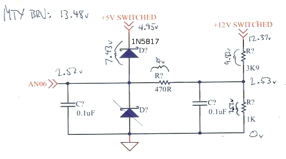
In other news, I built a BRV circuit today to measure the battery
voltage. I essentially copied the circuit from the RavAGE pdf
(thanks Dan!) I only had one Schottky diode left from the 5 pack
I bought for the MAP sensors (PN 1N5817), so I used it on the 5v
side on advice from Fred.

The BRV circuit works, but reads about 10% high. The MAP and AAP
sensors also read about 10% high. I suspect the Schottkys, but
I'm probably not qualified to speculate. ;)

I also discovered that a GM temperature sensor threads into a
hole on the cylinder head. This will simplify the CHT install
greatly.

[edit] Oh, regarding the 24and1 wheel, I did clean it up a bit.
It had a little surface rust on it which I polished off, the
perils of mild steel, I guess. It was clean going in.

[re tuning]
I'm not looking to push the timing as far as I can, I want det
cans for safety, more than anything, and also to get a feel for
what an engine sounds like with an ear pressed up against the
block. My goals are pretty conservative.


sim
<@TekniQue> but in the end, it's code that makes a computer useful
User avatar
Fred
Moderator
Posts: 15431
Joined: Tue Jan 15, 2008 2:31 pm
Location: Home sweet home!
Contact:

Re: sim's Volvo 245 comments

Post by Fred »

sim wrote:Bosch starter can accelerate the crank faster than you expected.
Nah, it comes down to compression and friction vs starter. That log that I took shows it jumping right up to 280 RPM or so, which is great, BUT, then it shows it steady for a few readings, which is normal. The accel and decel is within a cycle, ie, on the up stroke the engine slows against compression, and on the down stroke it is accelerated by the compression AND the starter. What it seems like to me, and Josh used an old worn engine too, is that there is very little bearing friction (loose clearances) and good compression. In any case, it varies engine to engine, was always meant to be configurable, hence raw values and not defines stuffed in there, and I have a master plan to make it even more awesome.
I added some #ifdef blocks to open the window up to 500-2000 as you suggested.
Overkill, but fine. I suggested that you stuff it in there because I don't want another commit with that data when I'm going to change it anyway, and because that decoder is used on the 4age too, which despite 10.5:1 compression, and good ring seal, was fine :-)
I went down and loaded the new build on the EMS and fired it up a couple of times. The sync loss while cranking is gone, it fired up and ran for several minutes with the sync loss value holding at zero in MTX.

Looks like you were dead on Fred, good call!
:-) I'd like to see a short log, I bet it starts faster now.
The BRV circuit works, but reads about 10% high. The MAP and AAP sensors also read about 10% high. I suspect the Schottkys, but I'm probably not qualified to speculate. ;)
I said that yesterday, and would have agreed, but then you measured V drop across the series resistors at zero and I changed my mind. Let me know when a good time to work with you is so we can do test, change tactic, do test, etc and figure it out in one session.
I also discovered that a GM temperature sensor threads into a hole on the cylinder head. This will simplify the CHT install greatly.
Does that hole enter the coolant galleries? If so, cool. If not, it may still be usable, but could be laggy and inaccurate.
[edit] Oh, regarding the 24and1 wheel, I did clean it up a bit. It had a little surface rust on it which I polished off, the perils of mild steel, I guess. It was clean going in.
I was more concerned with the edge quality. The light diffuses off the edges, and if a dag is hanging out it could either block light prematurely or make it arrive earlier. This is why the nissan ones are VERY thin (and LT1 too) to reduce diffraction. The yoshi one is thicker, but that doesn't concern me. What did was the roughness from the cutting process, but not very much. I was supposed to take one, but I put it down and forgot it. It doesn't matter much for now as my CAS sensor is dead anyway, and I have no drill :-)

Fred.
DIYEFI.org - where Open Source means Open Source, and Free means Freedom
FreeEMS.org - the open source engine management system
FreeEMS dev diary and its comments thread and my turbo truck!
n00bs, do NOT PM or email tech questions! Use the forum!
The ever growing list of FreeEMS success stories!
User avatar
sim
LQFP112 - Up with the play
Posts: 112
Joined: Thu Jun 02, 2011 8:17 pm

Re: sim's Volvo 245 comments

Post by sim »

Fred wrote:
I also discovered that a GM temperature sensor threads into a hole on the cylinder head. This will simplify the CHT install greatly.
Does that hole enter the coolant galleries? If so, cool. If not, it may still be usable, but could be laggy and inaccurate.
Yes, it replaces a "Wax valve", some kind of temperature dependent
air valve in the head. (It's a ~$100 sensor!) As luck has it, the
probe part of the sensor is almost exactly the same length as the GM part,
though a little slimmer, and has the same diameter and thread
pitch.

My engine has something that looks like a placeholder in its
place, (the turbo'ed B21FT has the proper wax valve installed)
but it should spin out and accept a GM coolant sensor. I just
need to acquire a 22mm deep socket.

The one-wire coolant temp sensor that feeds the cluster temp
gauge is separate, so, unlike the tach, the temp gauge will
continue to work. That gauge is very useful, so that is a win.

The GM CHT sensor can hook up to AN01.

Other things to think about soon:
I have a knocksense from http://viatrack.ca. It
produces a 5v logic signal with a pulse width dependent on knock
intensity. I can wire it up to AN11, for now. it is coarser than
using det cans, but it goes into the logs, so it can be
correlated to the tune (I don't expect to be pushing things for
a long while, but good logs are invaluable).

I have a couple of GM IAT sensors, the open type with the
thermistor exposed for maximum speed. One of these can hook up to
AN00 using the RavAGE circuit. I'll stuff the sensor into the
intake tract somehow.

Heh, my engine runs fairly well already, now I'm into improvement
territory.
<@TekniQue> but in the end, it's code that makes a computer useful
User avatar
Fred
Moderator
Posts: 15431
Joined: Tue Jan 15, 2008 2:31 pm
Location: Home sweet home!
Contact:

Re: sim's Volvo 245 comments

Post by Fred »

sim wrote:Yes, it replaces a "Wax valve", some kind of temperature dependent air valve in the head. <snip> I just need to acquire a 22mm deep socket.
Cool! :-)
The GM CHT sensor can hook up to AN01.
Yep! :-)
I have a knocksense from http://viatrack.ca. It produces a 5v logic signal with a pulse width dependent on knock intensity. I can wire it up to AN11, for now.
Yep, knock sensing isn't high on the priority list, but as you say, you can get it logged via a number of methods, ADC input being one. I'll have a think about it. These units have variable performance, so I'm unsure how keen I am to support such a signal. I think time might be better spent on the TI chip solution. We will see. One thing I could do is add another custom/default file pair and give you some code to try in that. LOTS of other things to do first, though. Number one on the list is fixing the ADC readings.
I have a couple of GM IAT sensors, the open type with the thermistor exposed for maximum speed. One of these can hook up to AN00 using the RavAGE circuit.
Cool! You may as well hook the other one up too and put it somewhere else. Ideas below.
I'll stuff the sensor into the intake tract somehow.
Be careful! You do not want this in the intake close to the engine. You want this close to the front of the car, not close to the exhaust manifold parts, not behind the radiator, having air drawn past it from the engine, not likely to get wet, not getting cooked by the headlight, etc. You pretty much want it right between headlight and radiator, or in the guard/fender near the front wheel, or something. I don't know if you were following my discussion with Herve in the user channel, but he had issues with this on his MS2 MX5 and followed my advice and ended up with a much better running car. Once you're boosted, it will need to go on the outlet of the intercooler, right next to the cooler, right in the front bumper or close to it.

Image

Mine is not visible in that pic, not installed at that point, but lives just after the first coupler on the inside of the shiny chinese mandrel bend to least disrupt the airflow. It's always read accurately for me and is on the opposite side to the exhaust/turbo and so far forward that it would never get hot air on the outside from the radiator output.

Put your spare one in another place and attach it to the MAT pin so we get temp numbers out of it. Interesting places to log will be closer to the intake manifold in the tract, ambient air temp in the front bumper, close to the exhaust, etc.
Heh, my engine runs fairly well already, now I'm into improvement territory.
Me first, me first! :-) Let's make sure the setup of the system on the car and the basic code is spot on before we go too much further or do any significant tuning.

Fred.
DIYEFI.org - where Open Source means Open Source, and Free means Freedom
FreeEMS.org - the open source engine management system
FreeEMS dev diary and its comments thread and my turbo truck!
n00bs, do NOT PM or email tech questions! Use the forum!
The ever growing list of FreeEMS success stories!
User avatar
Fred
Moderator
Posts: 15431
Joined: Tue Jan 15, 2008 2:31 pm
Location: Home sweet home!
Contact:

Re: sim's Volvo 245 comments

Post by Fred »

For the record:

Sim made me this pretty little picture:

Image

And I checked the code out and it was mint, so then I checked my TA card and....
MeOnIRC wrote:[20:42] <Cheetah> Simis, yes, I know what the issue is. I need to crack out my bench gear to prove it, but I'm surprised and I'll tell you exactly how to fix it. It involves your soldering iron :-)
[20:42] <Cheetah> seank-efi this affects you and Preston also.
[20:53] <Cheetah> simis: measure V drop across R5 which is close to the CAN1 header and confirm that it's about 0.37V or http://www.google.com/search?hl=en&safe ... 0.8.1l19l0
[20:54] <diyefi-bot> 4.95 - ( (1023/((1023 * MTXVolts) / 24.500)) * PinVolts) - Google Search
[20:54] <Cheetah> or the result of that
[20:54] <Cheetah> (assuming your batt V isnt the same as when you last measured...)
[20:55] <Cheetah> If that checks out, which it will, bridge R5 and check out your shiny new map and brv readings :-)
[20:55] <Cheetah> and if the values then look good, I'll wait for you to setup some temp sensors, then I'll write you some shiny new code
Enjoy! :-)

Fred.
DIYEFI.org - where Open Source means Open Source, and Free means Freedom
FreeEMS.org - the open source engine management system
FreeEMS dev diary and its comments thread and my turbo truck!
n00bs, do NOT PM or email tech questions! Use the forum!
The ever growing list of FreeEMS success stories!
User avatar
Fred
Moderator
Posts: 15431
Joined: Tue Jan 15, 2008 2:31 pm
Location: Home sweet home!
Contact:

Re: sim's Volvo 245 comments

Post by Fred »

Additionally, my numbers line up with theory too... :

Code: Select all

7 P Reference supply current 2 ATD blocks on IREF — — 0.500 mA
8 P Reference supply current 1 ATD block  on IREF — — 0.250 mA
I measured 0.3V across my 1k R5 :

http://www.google.com/search?hl=en&safe ... l0.1.1l2l0

0.3mA!!!! :-)

Carry on!

Fred.
DIYEFI.org - where Open Source means Open Source, and Free means Freedom
FreeEMS.org - the open source engine management system
FreeEMS dev diary and its comments thread and my turbo truck!
n00bs, do NOT PM or email tech questions! Use the forum!
The ever growing list of FreeEMS success stories!
User avatar
sim
LQFP112 - Up with the play
Posts: 112
Joined: Thu Jun 02, 2011 8:17 pm

Re: sim's Volvo 245 comments

Post by sim »

Fred wrote:For the record:

Sim made me this pretty little picture:

Image

And I checked the code out and it was mint, so then I checked my TA card and....
MeOnIRC wrote:[20:42] <Cheetah> Simis, yes, I know what the issue is. I need to crack out my bench gear to prove it, but I'm surprised and I'll tell you exactly how to fix it. It involves your soldering iron :-)
[20:42] <Cheetah> seank-efi this affects you and Preston also.
[20:53] <Cheetah> simis: measure V drop across R5 which is close to the CAN1 header and confirm that it's about 0.37V or http://www.google.com/search?hl=en&safe ... 0.8.1l19l0
[20:54] <diyefi-bot> 4.95 - ( (1023/((1023 * MTXVolts) / 24.500)) * PinVolts) - Google Search
[20:54] <Cheetah> or the result of that
[20:54] <Cheetah> (assuming your batt V isnt the same as when you last measured...)
[20:55] <Cheetah> If that checks out, which it will, bridge R5 and check out your shiny new map and brv readings :-)
[20:55] <Cheetah> and if the values then look good, I'll wait for you to setup some temp sensors, then I'll write you some shiny new code
Enjoy! :-)

Fred.
You nailed it Fred.

Image
Technologic Arts R5

I jumpered R5 and the error dropped to 0.14v, from about 1.1v.

Some notes about the modification:

Watch the soldering. I desoldered R5 and replaced it with the
trimmed leg of a resistor. You have to solder both sides of each
leg. The vias have very narrow pads around them. I had initially
soldered the jumper inadequately, and wound up with a value of
24.5v in MegaTunix.

I lifted a trace with the heat I put into the board. Not a big
deal to fix, but a high resolution picture taken of the board
prior to abusing it would have been very helpful.

I also added circuits for TPS, CHT, and IAT today. I did a quick
sanity check with an IAT sensor and it looks okay. I need to
actually install CHT and IAT sensors into the car, and build a
harness for them before I can log. I did get a 22mm six-point
deep socket the other day for $2, so I'll be able to pull the old
"wax valve" and replace it with a GM CHT sensor without trouble.

IAT sensor just requires a hole drilled into the carb air intake
hose. Maybe a little sealant too.

TPS will wait until EFI. I still have to fab an adapter plate to fit
the Volvo 960 TPS I have to the 740 throttle body.

The car still drove after all the soldering!
Two tanks of gas so far!
<@TekniQue> but in the end, it's code that makes a computer useful
User avatar
Fred
Moderator
Posts: 15431
Joined: Tue Jan 15, 2008 2:31 pm
Location: Home sweet home!
Contact:

Re: sim's Volvo 245 comments

Post by Fred »

sim wrote:I jumpered R5 and the error dropped to 0.14v, from about 1.1v.
Your 0.14V comes down to two things, both of which you can tune out with a single setting in the code:

1) resistor tolerance
2) regulator voltage

The thing to configure is batteryVoltageRange and although I know it doesn't matter, I think you should, just because :-)
I had initially soldered the jumper inadequately, and wound up with a value of 24.5v in MegaTunix.
VRH was floating and falling close to zero making the world look MUCH bigger than it was :-)
a high resolution picture taken of the board prior to abusing it would have been very helpful.
If you're unsure, just ask, I can snap and upload for you in minutes.
I also added circuits for TPS, CHT, and IAT today.
Sweet! :-)
IAT sensor just requires a hole drilled into the carb air intake hose. Maybe a little sealant too.
Can you please upload an engine bay shot showing the layout from bumper to carb and where you intend to put it. I don't want you to put it in a bad place and then have to move it later. Trust Fred and let's do it right first time :-)
The car still drove after all the soldering! Two tanks of gas so far!
Congratulations! :-)

Fred.
DIYEFI.org - where Open Source means Open Source, and Free means Freedom
FreeEMS.org - the open source engine management system
FreeEMS dev diary and its comments thread and my turbo truck!
n00bs, do NOT PM or email tech questions! Use the forum!
The ever growing list of FreeEMS success stories!
User avatar
sim
LQFP112 - Up with the play
Posts: 112
Joined: Thu Jun 02, 2011 8:17 pm

Re: sim's Volvo 245 comments

Post by sim »

Here is a shot of the engine bay:
Image

The airbox is just to the left of the battery. My plan is to
mount the IAT sensor in either the airbox, or into the air
hose that runs to the carb, close to the airbox.

I don't think there will be any heat soak issues there, and it is
very close to the outlet position on a stock 240 intercooler, so
the upgrade path is clear.
<@TekniQue> but in the end, it's code that makes a computer useful
User avatar
Fred
Moderator
Posts: 15431
Joined: Tue Jan 15, 2008 2:31 pm
Location: Home sweet home!
Contact:

Re: sim's Volvo 245 comments

Post by Fred »

Cool :-) Sounds like you were going to do it right anyway!
DIYEFI.org - where Open Source means Open Source, and Free means Freedom
FreeEMS.org - the open source engine management system
FreeEMS dev diary and its comments thread and my turbo truck!
n00bs, do NOT PM or email tech questions! Use the forum!
The ever growing list of FreeEMS success stories!
Post Reply