Spudmn's Puma board build

All home-built FreeEMS implementations without a forum of their own, usually TA-based.
Post Reply
User avatar
Spudmn
LQFP112 - Up with the play
Posts: 232
Joined: Thu Feb 10, 2011 12:27 am
Location: Auckland, NZ

Spudmn's Puma board build

Post by Spudmn »

I Picked up my Puma board Last night.

I have already ordered my Freescale samples and they should be on there way soon.

My build will be very simple and I will only be running wasted spark to begin with.

I knew that I had a box that I found years ago and thought that it would be the right size.

I just found it and it's great fit.

Image

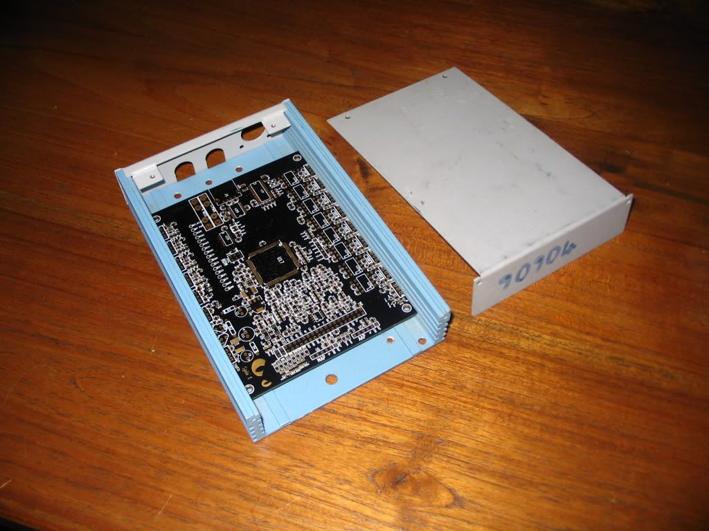
OK the the colour is Sh*t but I can fix that with paint.

Some of the pads are a bit close to the pads but I can deal with that.

My next step is to put on the power supply components and check all the voltages are correct.

You don't want to find that your voltages are not right when you have the Micro soldered on.

I have found most of my sensors that I have been collecting over the years but I still can't find my ignition drivers. Might be a trip to pick-a-part coming up.

Aaron
User avatar
nitrousnrg
LQFP144 - On Top Of The Game
Posts: 468
Joined: Tue Jun 24, 2008 5:31 pm

Re: Spudmn's Puma board build

Post by nitrousnrg »

Awesome news!!

Take a look at the docs before soldering things. Besides of that, you'll fine. Ask about any doubts man.

That case really fits the board. Where was it used for in its other life?
Marcos
User avatar
Spudmn
LQFP112 - Up with the play
Posts: 232
Joined: Thu Feb 10, 2011 12:27 am
Location: Auckland, NZ

Re: Spudmn's Puma board build

Post by Spudmn »

nitrousnrg wrote:Awesome news!!

Take a look at the docs before soldering things. Besides of that, you'll fine. Ask about any doubts man.

That case really fits the board. Where was it used for in its other life?
Will Do.

I thought that you designed the board to fit my box :lol:

I don't know what the box was used for. I picked it up from a surplus electronics store.
User avatar
Spudmn
LQFP112 - Up with the play
Posts: 232
Joined: Thu Feb 10, 2011 12:27 am
Location: Auckland, NZ

Re: Spudmn's Puma board build

Post by Spudmn »

nitrousnrg wrote: That case really fits the board. Where was it used for in its other life?

It used to house a Autosec Cellular Transmitter for an alarm system.

It has a much better use now :D
User avatar
Spudmn
LQFP112 - Up with the play
Posts: 232
Joined: Thu Feb 10, 2011 12:27 am
Location: Auckland, NZ

Re: Spudmn's Puma board build

Post by Spudmn »

My CPU has just arrived. :D

I will have to get my A into G and get the other parts sorted.

What is my best option with regards to the BDM. build one? borrow one?
User avatar
nitrousnrg
LQFP144 - On Top Of The Game
Posts: 468
Joined: Tue Jun 24, 2008 5:31 pm

Re: Spudmn's Puma board build

Post by nitrousnrg »

If you can, borrow one!
Marcos
User avatar
Fred
Moderator
Posts: 15431
Joined: Tue Jan 15, 2008 2:31 pm
Location: Home sweet home!
Contact:

Re: Spudmn's Puma board build

Post by Fred »

nitrousnrg wrote:If you can, borrow one!
I am still around for a few weeks, if you're quick, you can use mine. Perhaps just build the thing up and bring it over with a win laptop to burn from?

Marcos, can you assist Spudmn in getting a cpu/powersupply only board setup built correctly asap?

Fred.
DIYEFI.org - where Open Source means Open Source, and Free means Freedom
FreeEMS.org - the open source engine management system
FreeEMS dev diary and its comments thread and my turbo truck!
n00bs, do NOT PM or email tech questions! Use the forum!
The ever growing list of FreeEMS success stories!
User avatar
nitrousnrg
LQFP144 - On Top Of The Game
Posts: 468
Joined: Tue Jun 24, 2008 5:31 pm

Re: Spudmn's Puma board build

Post by nitrousnrg »

spudmn, populating these components you'll be able to program the serial monitor:
http://nitrousnrg.imgur.com/puma#4m0Og

Does someone have codewarrior over there?
Marcos
User avatar
Spudmn
LQFP112 - Up with the play
Posts: 232
Joined: Thu Feb 10, 2011 12:27 am
Location: Auckland, NZ

Re: Spudmn's Puma board build

Post by Spudmn »

I assume that I just need 5V on the Micro. Decoupling caps, Xtal and PLL and the DBM connector as a minimum system?

I should be able to hack something up pretty quick.

Will I need the 5V Switched as well?

There is something Fred said about a CAP for the BDM that needs to go in the documentation. What is this?
Last edited by Spudmn on Mon Mar 21, 2011 10:05 am, edited 1 time in total.
User avatar
nitrousnrg
LQFP144 - On Top Of The Game
Posts: 468
Joined: Tue Jun 24, 2008 5:31 pm

Re: Spudmn's Puma board build

Post by nitrousnrg »

no switched 5v needed. You need it when you're going to load freeems firmware if the FT232 tkes 5v from the board. You'd need the load/run header by that time too.

The cap hack is to delay the mcu start, but its safe to program it without the capacitor. You'll see that the bdm programs and verifies it successfully without cap
Marcos
Post Reply