Page 14 of 18
Re: Spudmn's Puma board build
Posted: Sat Jan 21, 2012 9:33 am
by Spudmn
I got 2 sensors today that should do the trick.
Post an aerial shot of your engine bay and I'll tell you what I think

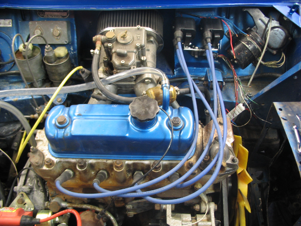
The radiator is missing in this shot but it is on the right.
Re: Spudmn's Puma board build
Posted: Sat Jan 21, 2012 10:51 am
by Fred
"What's that?" - "It looks like a robot from star wars" - "Like r2d2" - wife. Can't say I see the similarity, myself, but, perhaps you'll get a giggle from it.
I was hoping for a bit wider, but I've spent enough time crying under the bonnet of a mini to know that there isn't much more of it to show :-)
Tricky. Chuck one of them on, behind, beside, under, the air filter in your cut out, and the other out the front of the car somewhere on the gearbox side, and get some data and we'll go from there. Sound good? Again, for ign only, it's almost irrelevant anyway, so don't worry too much.
Fred.
Re: Spudmn's Puma board build
Posted: Mon Feb 06, 2012 12:52 am
by Fred
How are you getting on with the old board? If you can't suss it out, maybe we screwed up the BDM load? Preston has ordered one of those open source BDMs from China, so I'm sure he'll be keen to help you verify that you have a good SM burn on there. He needs to redo the CPU on my TA card that he has, and one of his Puma boards was blank too, so he'll be getting it working at some point. Just FYI.
Re: Spudmn's Puma board build
Posted: Tue Feb 07, 2012 1:19 am
by Spudmn
Great News. I will have to talk nicely to Preston.
Re: Spudmn's Puma board build
Posted: Sun Mar 11, 2012 8:42 am
by Spudmn
I have been so busy at work for the last 2 months that I have had very little time for any FreeEMS projects. I was supposed to compete in a Grasskhana today but it got rained out. So I started to get the Puma board off the work bench and install it into the car. I managed to get it hooked up and took it for its first test drive on FreeEMS. Very happy. No tuning but it runs sweet.

This is also the first time I have run the engine since I put in the balance tube. Now when the car is running on the distributor, the idle sounds different. Anyway I got another log of the map and this looks a lot better.
I can't seem to get the Puma fired up unless I have it plugged into my laptop.
The Puma that I am using doesn't have the transistor for the USB chip, is this the reason?
Now I have a bit more time I want to get my Puma working and get everything installed in the car. I haven't got long till the next event and I want to be running FreeEMS for that.
Re: Spudmn's Puma board build
Posted: Sun Mar 11, 2012 6:27 pm
by Fred
Congratulations on the first drive! Did you take a video for your fans? :-)
I took a look at your log earlier and it looks suspicious! The first RPM reading is 400 odd and there is NO sag in the very low battery voltage when starting.
Vacuum wise, it's going to be a c*** to tune with only 22kPa or range from idle to WOT. This is why I said it was a shame that you did the balance tube "hard coded". I think the best approach for this setup, as long as you have the carbs, is either going to be TPS based or dual MAP sensor based such that you can catch the low values with the correct timing and not have the lows diluted by the highs on the other side. At least it's fairly consistent, now, though. There are still some obvious patterns in the signal too, and it's still noisy but much better for obvious reasons. You can see the siamese nature of it with paired numbers :-)
I wonder what is causing the idle sound difference, likely just "amount of timing". Does it idle low or high compared to the dizzy?
The RPM is still a bit wobbly too, part of that is the code, but I'm guessing part is the cams/rough idle. Part could also be the design of the trigger wheel and mag flux issues. I really need to implement the edge logger for these missing tooth installs, it would make it extremely obvious what was going on.
Re USB, Puma, PNP, yes. Install a PNP with the correct cut traces/jumpers and live happily ever after.
I wouldn't mind putting an #ifdef SPUDMN block in for temporary dual MAP if you're up for setting it up. You could solder the second on in where the AAP is supposed to go, or run dual externals. That will get you a nice low signal that you could more easily tune with. The way it is right now you'll have to be very careful and conservative to avoid getting too much timing at the wrong loads. Then again, as pointed out by a recent arrival, most of the timing is RPM based, so the vacuum aspect just gets you more economy. I guess you can race on that :-)
Glad you're liking the way it's driving, just be careful about timing on that little vacuum range. If you stick with it, you'll need to roll with an axis that goes from 60 - 100 kPa in 16 steps or just ignore the bottom half of the table, which will never get used. I'd like to see a datalog of you driving it with it setup like this, it would be interesting to see the real range in use.
Fred.
Re: Spudmn's Puma board build
Posted: Sun Mar 11, 2012 11:54 pm
by Spudmn
Fred wrote:Congratulations on the first drive! Did you take a video for your fans?
Not yet, but I will see what I can do.
Fred wrote:I took a look at your log earlier and it looks suspicious! The first RPM reading is 400 odd and there is NO sag in the very low battery voltage when starting.
That would be because I was running the Puma on the bench, off a 12V supply.
Fred wrote:I wonder what is causing the idle sound difference, likely just "amount of timing". Does it idle low or high compared to the dizzy?
It’s not so much of a speed thing, just a different sound. Almost like the overlap on the intake is different. I am not too worried about it as it still runs well.
Fred wrote:Re USB, Puma, PNP, yes. Install a PNP with the correct cut traces/jumpers and live happily ever after.
OK I will get on to that
Fred wrote:I wouldn't mind putting an #ifdef SPUDMN block in for temporary dual MAP if you're up for setting it up. You could solder the second on in where the AAP is supposed to go, or run dual externals. That will get you a nice low signal that you could more easily tune with. The way it is right now you'll have to be very careful and conservative to avoid getting too much timing at the wrong loads. Then again, as pointed out by a recent arrival, most of the timing is RPM based, so the vacuum aspect just gets you more economy. I guess you can race on that
I think I might try dual externals. The Cooper S models had no vacuum advance at all so if I run out of time I can race with RPM based advance only.
Fred wrote:Glad you're liking the way it's driving, just be careful about timing on that little vacuum range. If you stick with it, you'll need to roll with an axis that goes from 60 - 100 kPa in 16 steps or just ignore the bottom half of the table, which will never get used. I'd like to see a datalog of you driving it with it setup like this, it would be interesting to see the real range in use.
I will get some real data logs next time I take it for a run. I don’t want to piss off the neighbours too much.

Re: Spudmn's Puma board build
Posted: Mon Mar 12, 2012 1:19 am
by Fred
Spudmn wrote:I don’t want to piss off the neighbours too much. :lol:
I thought you were out west? They should be on the front lawn (next to that kingswood shell) with a beer in one hand and the other in a fist in the air cheering you on :-)
Re: Spudmn's Puma board build
Posted: Mon Mar 12, 2012 1:35 am
by Spudmn
Fred wrote:Spudmn wrote:I don’t want to piss off the neighbours too much.
I thought you were out west? They should be on the front lawn (next to that kingswood shell) with a beer in one hand and the other in a fist in the air cheering you on
ROFL!
Re: Spudmn's Puma board build
Posted: Tue Mar 27, 2012 8:42 pm
by Spudmn
Bugger !!
I have had a run of bad luck with my Puma board.
After the perfect run the other week. I tried to start the car again this weekend. It would not fire up. When I did get it running it sounded like it was on only 2 cylinders.
After some investigation I found that 3 vias near the XOR had gone open circuit. I think that there was some bad flux sitting in the hole and it had eaten them away. I gave the whole board a good ultrasonic clean and fixed the vias.
Then last night I found that one of my outputs on my J722T Ignition module has blown up.
Gutted!

Looks like I will be making a trip to Pick-a-Part this weekend.