Page 2 of 4
Re: uROEFI
Posted: Fri Feb 21, 2014 12:48 am
by Fred
m3ltd0wn wrote:they are different from what they used and the board is not for commercial purposes.
This doesn't mean that you couldn't be causing a provable financial loss with clear intent to use firmware without a license that permits that use.
having a stable code that can run 60-2 trigger wheel of the rally/drag car
LOL @ calling ms1 "stable code". The missing tooth code in ms1 is an absolute joke, nothing more. I have proof, too.
Anyway I think I violate only the software licensing
You do violate this, however if you represent a potential financial loss to B&G through publication of compatible hardware of which they get no profit cut, then they could swing lawyers. On the other hand, you're in Europe, however James Murray has been threatening to swing lawyers at Euro cloners, so beware.
Fred.
Re: uROEFI
Posted: Fri Feb 21, 2014 7:59 am
by m3ltd0wn
Well, it will run on XDP512, so it is not a clone, HC908 is only for testing

I wouldn't bother making a ms clone, there are lots of it out there
Let us concentrate on jaguar/ravage hardware, it is more interesting than m$
I was looking on injector drivers schematics, and I wanted to know if I got this right:
+12v from injector will come in to INJ output of the board, and injector grounds will be joined and wired to injgnd?
Re: uROEFI
Posted: Fri Feb 21, 2014 9:13 am
by m3ltd0wn
a few pictures with the IGBT module, up to 6 cylinder wasted COP, has the VR sensor input circuit based on LM1815(in case it is needed), this was the first revision, it needs larger traces from IGBTs to the COPs, and other fuse socket.
Re: uROEFI
Posted: Fri Feb 21, 2014 9:24 am
by walinsky
m3ltd0wn wrote:Understood

I won't publish the m$ compatible cpu module schematics, anyway they are different from what they used and the board is not for commercial purposes.
The MC908GP32CFBE pcb board will be used for testing the inputs and outputs, and see how well the mainboard behaves in harsh environments (having a stable code that can run 60-2 trigger wheel of the rally/drag car, and because I am familiar with it, it will be easier to debug problems). Anyway I think I violate only the software licensing (using msns_extra hr code - outdated and not maintained anymore), as the hardware is way different then theirs.
After testing the crap out of this board I'll build the XDP512 cpu board and start developement around it since it is more powerfull.
Best regards,
m3ltd0wn
I don't know if rpm > 3k is already supported with a 60-2 trigger wheel.
Re: uROEFI
Posted: Fri Feb 21, 2014 11:18 am
by Fred
Will be, shortly after someone actually proves a need for it. A couple of cars have run 60-2 so far, but all garage queens with no/little (known to me, at least) tuning time put into them.
Meltdown, what's your real name? Even if only via PM for my eyes. Whatever it is, I would have two pins, and two wires for injector grounds, with all N FETs using it as a ground supply to ground their respective injectors. Jaguar is setup very configurably in this respect. It's confused everyone so far, so maybe it's not a good idea, however the old system meant potential ground imbalance depending on setup. I forget how ravage is setup, but likely well.
Fred.
Re: uROEFI
Posted: Fri Feb 21, 2014 12:33 pm
by m3ltd0wn
Vladimir is my name
Looking on the schematics of Jaguar injector drivers, I've used only two, I just need batch fire only (sequential injection is more like stress to me and only for emissions, rally cars don't care about emissions
) for simplicity and quick debug.
Now from the schematics, I see 12v rail to Led then to Zenner and straight to injector, common injector ground, and between +12v rail and ground is the omnifet, PWM0-1 activates the omnifet, so based on this schematic +12v of the injector will need to go straight to the mainboard plug, and grounds at engine bloc or head, this is uncommon here in europe, all the ECUs i've seen have a +12v rail from a relay to injectors (fused), and grounds of the injectors come from injector drivers from the ECU.
and the ignition driver schematics modified based on Fred's suggestions
Re: uROEFI
Posted: Fri Feb 21, 2014 1:15 pm
by Fred
Ummm, no, that's not how it works. Not on almost any cars at all. Maybe none.
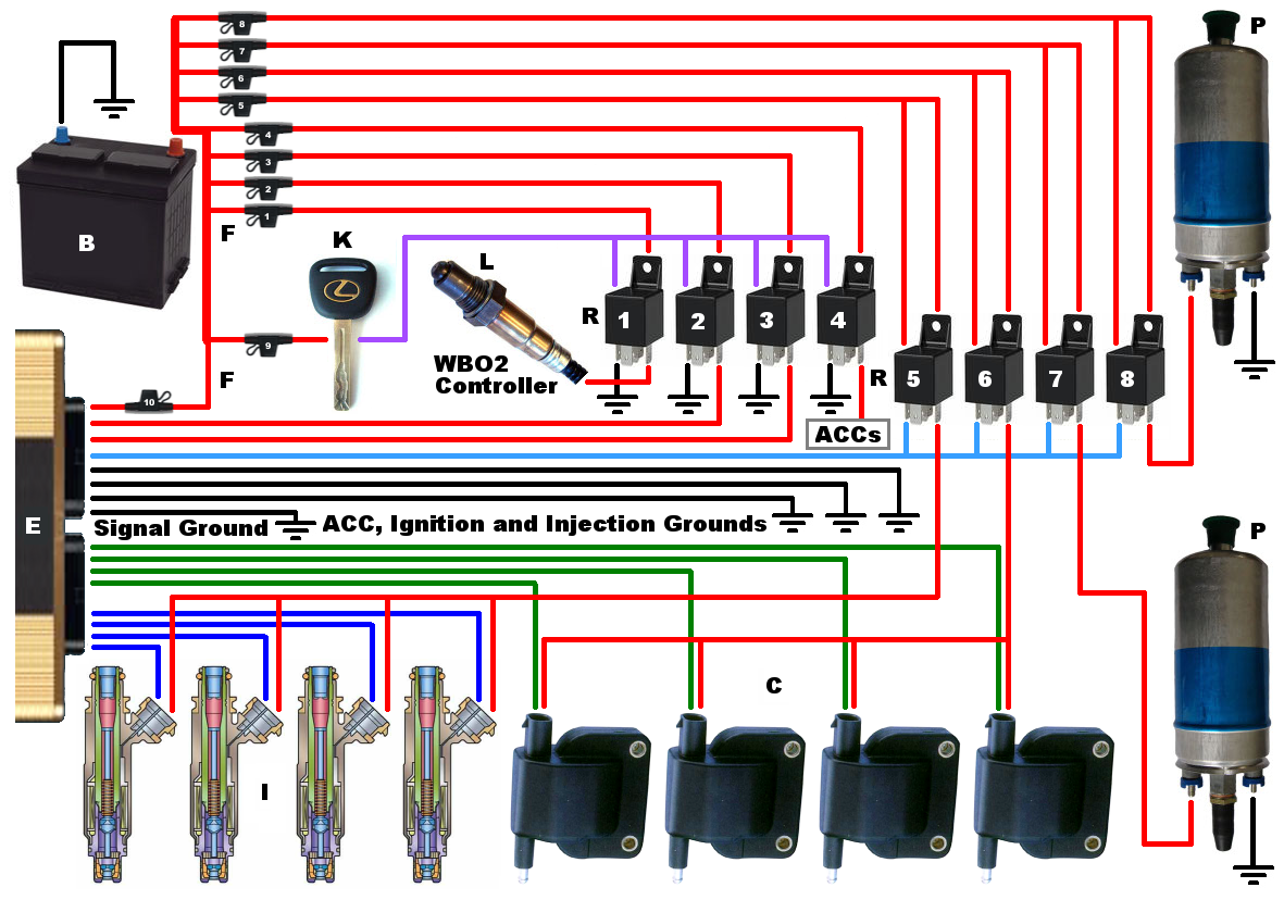
Maybe this will help:
Re: uROEFI
Posted: Fri Feb 21, 2014 2:01 pm
by m3ltd0wn
well, I can tell you for sure that on my stoc vw ecu, +12v rail was split for each injector, and the 4 ground wires from the ecu (gray red, gray blue, gray and gray green) were wired to the ground side of the injectors ... on bmw 325 ecu was the same thing, 6 ground wires fom ecu were wired to ground of the injectors, and +12v feed was from the relay box.
i would like to keep the same configuration to uROEFI because I'm planning on making it plug and play or at least keep the stoc ecu connector and wire from there the rest of the loom.
edit:
ok, I think i got it now, was confused at first about the schematic, so INJ-out is the signal for the injectors (GND switching), injgnd is the separate ground for the high current omnifet, and +12v rail there is just to lit the led ...
Re: uROEFI
Posted: Fri Feb 21, 2014 2:38 pm
by m3ltd0wn
ehehe, a little rough simulation of the injector circuit, for better understanding
Re: uROEFI
Posted: Fri Feb 21, 2014 8:31 pm
by m3ltd0wn
Active high circuit for activating launch control and table switching functions: