
I'll try to remember to clean out the .bak files next time, and from now on. I don't expect they would make sense to anyone other then me anyhow.
So far I've found a missing trace, connecting the power to the ignition. Oops. Also I've added freeEMS 1.0 A.XX to the component side copper. That way revision control will always be etched in.
I guess I can keep finding and populating component suppliers to the schematic BOM. Hmmm, what else can I do....
About the connection board, I'm not sure I can move the connection points around all that much, But little wires might allow connections from and to freeEMS to reside on different parts of the connection board then the freeEMS board. I'd kind of like something that allows you to unsnap and open it up. Perhaps the wires in between can allow for that. I think it's not that bad, something like 15 wires or so.
Any how just a thought.
DFH - Defacto FreeEMS Hardware in KICAD

Re: freeEMS_1.0 rev A KICAD
Awesome, yes!jharvey wrote:Oops. Also I've added freeEMS 1.0 A.XX to the component side copper. That way revision control will always be etched in.
So they would be wires to go from right by the CPU board connector to various places on your board? No, you must mean signal outs, since there's no real standard connector in there.
Certainly plunking a DB in there or even just a header row would be awesome... But space is really tight on the board as is.
Could you do it by section? A collection of pins for ignition, one for fuel, one for signals in, etc?
Re: freeEMS_1.0 rev A KICAD
The wires on this one leave in different p;aces. Here's a picture to show what I mean. Connections that leave the board are shown in red.
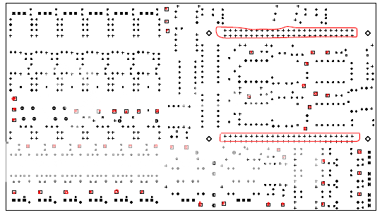
I was thinking the connector board and EMS board could open like a book with a series of wires as the binding. The CPU connector (and stand offs) would hold it shut normally. So what I'm saying is that the connector card doesn't need vias to line up with the vias in the above picture. You can lay it out flat, and solder wires from one to the other, then fold it up.
I was thinking the connector board and EMS board could open like a book with a series of wires as the binding. The CPU connector (and stand offs) would hold it shut normally. So what I'm saying is that the connector card doesn't need vias to line up with the vias in the above picture. You can lay it out flat, and solder wires from one to the other, then fold it up.
Re: freeEMS_1.0 rev A KICAD
Not worried about noise or cross talk issues?
The ones on the bottom left look like you could just tweak them to be on 0.100" centers, and get standard headers to make a stacked bord. If you could do it with enough of them, then very few would need to be wires.
Not sure I care.
The ones on the bottom left look like you could just tweak them to be on 0.100" centers, and get standard headers to make a stacked bord. If you could do it with enough of them, then very few would need to be wires.
Not sure I care.
Re: freeEMS_1.0 rev A KICAD
Correct not really concerned about cross talk. I laid the board out such that inputs are on the right / top ish, and very close to the CPU, shortening the antennas for these leads. The driving and power stuff is mostly right, and bottom ish. So if you kind of keep these grouped together, the signals should be fairly well isolated. If we get real concerned, we can use CAT5 for the digital wires. The twisted pair might help keep any extra noise down, but I really don't expect that to be an issue. After all they all end up in the harness right.
Re: freeEMS_1.0 rev A KICAD
So it's been a while since I posted to this thread.
I had a brain fart, that I thought I'd toss out here and see what folks thought of it. I was thinking of a quality test to ensure the PCB manufacturer used the correct copper. I was thinking of making a small trace or group of traces. Then run a current through the trace and see if it burns up. So if the MFG used 1 oz, copper instead of 2 oz, the trace would burn, but if it had 2 oz, it would be fine. If all is well, you shouldn't have a blemish on your board.
Is this a good idea? If so what would be a good current to run the test against. I'm was thinking of perhaps 1 amp because it matches the smaller on board fuse. However, that might be bit big for many folks. Perhaps a couple that work in the mA range.
-
SleepyKeys

- LQFP144 - On Top Of The Game
- Posts: 549
- Joined: Mon Feb 11, 2008 10:52 pm
- Location: Arizona
- Contact:

Re: freeEMS_1.0 rev A KICAD
Is that a real issue that some board manufacturers will try to pass you some 1oz copper boards when you ordered 2oz? Or would that be to check a batch from some other uncertain source?
If it's the former then I'd like to know which manufacturers are suspect so I make sure to avoid them. I would think that any respectable board manufacturer could be trusted or they wouldn't stay in business for very long.
Jean
If it's the former then I'd like to know which manufacturers are suspect so I make sure to avoid them. I would think that any respectable board manufacturer could be trusted or they wouldn't stay in business for very long.
Jean

Re: freeEMS_1.0 rev A KICAD
+1 Jean.
DIYEFI.org - where Open Source means Open Source, and Free means Freedom
FreeEMS.org - the open source engine management system
FreeEMS dev diary and its comments thread and my turbo truck!
n00bs, do NOT PM or email tech questions! Use the forum!
The ever growing list of FreeEMS success stories!
FreeEMS.org - the open source engine management system
FreeEMS dev diary and its comments thread and my turbo truck!
n00bs, do NOT PM or email tech questions! Use the forum!
The ever growing list of FreeEMS success stories!
Re: freeEMS_1.0 rev A KICAD
It's double perhaps tripple fold. It confirms the MFG hasn't porked you, it also confirms design intent. I've made predictions, are they right? It also confirm the person who ordered it, has specified 2 oz, not 1 oz.
It surely would suck if you put the parts in to find you had to remove them.
It surely would suck if you put the parts in to find you had to remove them.