
I'm not going to bother stripping the pcb file on the schematic release. I'm also not sure if I'll be adding the module library on the PCB release either.
Just a quick update, I've added some 3D to the TA card, and coppied the injector and ignition sections. Routing the ignition is fairly straight forward. But the injection is getting a bit tough. I may need to inquire about some kind of flex cable, or we might have to ease up on some of the min requirements. Time will tell if I can get it all glued together. Also I don't think I'll be able to honor having the connections to the CPU the way they are drawn on the schematic. I'm going to have to make some changes. Right now driving circuits perfer the lower half of the TA card, and the data preferes the top half.
Also Fred you'll be happy, the CPU LED's are gone, as well as two of the AN protects, and I'll likely redraw the AN protects to allow for 7 not 8. However, the current sense, and temp FET seem insignificant. So they are still there, but will be removed if it makes it easier to route the injector drive lines.
Any how, progress, and shortly we should have a PCB. Now it's back to the bump and grind.
DFH - Defacto FreeEMS Hardware in KICAD

Re: freeEMS_1.0 rev A KICAD
Wow, it's starting to look really good.
What CPU LEDs?
I was going to say that flex cables are really bad, but actually, I keep forgetting this is a test mule, so it's no big thing in my opinion.
There's always the option of putting some ignition on one side, and some on the other... If it helps the routing. Kinda weird, but heck, most will only be using for of each anyway.

Re: freeEMS_1.0 rev A KICAD
I've said this before and I'll say it again. You can't just go shuffling pins around to suit the layout. The layout needs to be shuffled to suit the pin usages based on what they can and can't do. In most cases it is pretty much non negotiable. I still haven't even nailed them down for you yet, and given the current status of my laptop, I won't be able to until the weekend at the earliest. I did warn you about rushing ahead, it may be fun and everything, but it's a useless piece of fibreglass without some functional code that is pin compatible with it.
Sorry to be hard nosed about it, but there really is no other way.
Fred.
Sorry to be hard nosed about it, but there really is no other way.
Fred.
DIYEFI.org - where Open Source means Open Source, and Free means Freedom
FreeEMS.org - the open source engine management system
FreeEMS dev diary and its comments thread and my turbo truck!
n00bs, do NOT PM or email tech questions! Use the forum!
The ever growing list of FreeEMS success stories!
FreeEMS.org - the open source engine management system
FreeEMS dev diary and its comments thread and my turbo truck!
n00bs, do NOT PM or email tech questions! Use the forum!
The ever growing list of FreeEMS success stories!
Re: freeEMS_1.0 rev A KICAD
I've said it before and I'll say it again.
Here's FreeEMS 1.0 A.18 P.01 it can be found here
https://sourceforge.net/project/showfil ... _id=625068
This release is basically routed, other than getting then signals to the CPU, and removing one AN protect from the schematic. Here's a 3D pic.
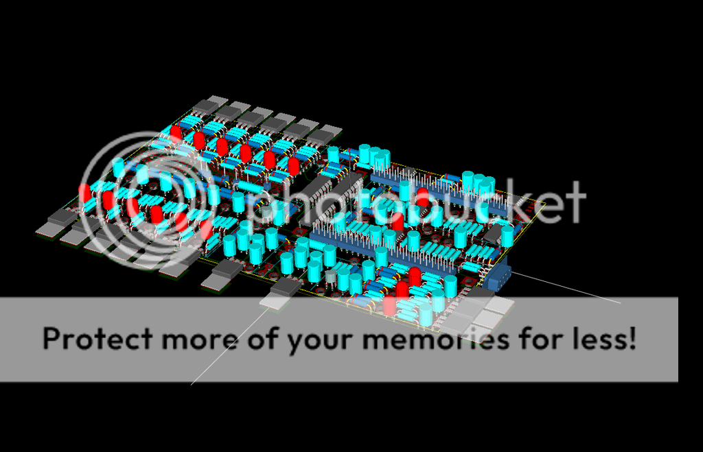
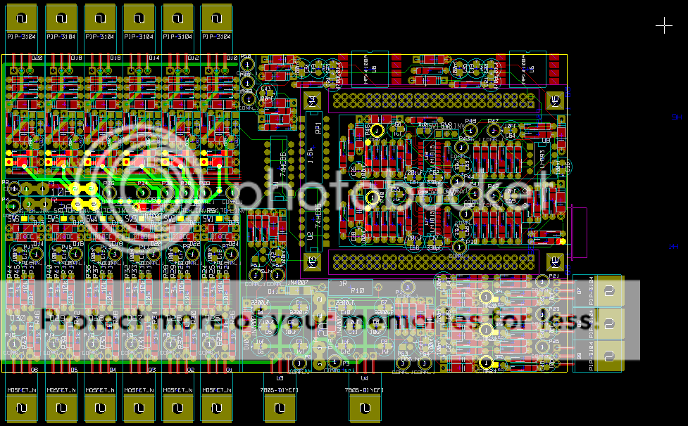
Here's a 2D pic.
This weekend I plan on asking for folks to look at it an give it a detailed review. Right I know of a couple of things that should be ironed out a bit more, but I want to get a copy out there showing it's basically done. I'd ball park it as 90% to 95% done.
Here's FreeEMS 1.0 A.18 P.01 it can be found here
https://sourceforge.net/project/showfil ... _id=625068
This release is basically routed, other than getting then signals to the CPU, and removing one AN protect from the schematic. Here's a 3D pic.
Here's a 2D pic.
This weekend I plan on asking for folks to look at it an give it a detailed review. Right I know of a couple of things that should be ironed out a bit more, but I want to get a copy out there showing it's basically done. I'd ball park it as 90% to 95% done.
Re: freeEMS_1.0 rev A KICAD
I've said it before and I'll say it again :
WOW
Nice work Mr Harvey! :-)
WOW
Nice work Mr Harvey! :-)
DIYEFI.org - where Open Source means Open Source, and Free means Freedom
FreeEMS.org - the open source engine management system
FreeEMS dev diary and its comments thread and my turbo truck!
n00bs, do NOT PM or email tech questions! Use the forum!
The ever growing list of FreeEMS success stories!
FreeEMS.org - the open source engine management system
FreeEMS dev diary and its comments thread and my turbo truck!
n00bs, do NOT PM or email tech questions! Use the forum!
The ever growing list of FreeEMS success stories!
Re: freeEMS_1.0 rev A KICAD

edit: Doesn't the comp board already have serial coms??
Re: freeEMS_1.0 rev A KICAD
ROFL :-)
He's just placed it there to look right. That was my first thought too and there are no pads for one on the flat layout ;-)
He's just placed it there to look right. That was my first thought too and there are no pads for one on the flat layout ;-)
DIYEFI.org - where Open Source means Open Source, and Free means Freedom
FreeEMS.org - the open source engine management system
FreeEMS dev diary and its comments thread and my turbo truck!
n00bs, do NOT PM or email tech questions! Use the forum!
The ever growing list of FreeEMS success stories!
FreeEMS.org - the open source engine management system
FreeEMS dev diary and its comments thread and my turbo truck!
n00bs, do NOT PM or email tech questions! Use the forum!
The ever growing list of FreeEMS success stories!
Re: freeEMS_1.0 rev A KICAD
Makes me wonder, why cut off the bottom half of that picture. Paul Harvey might want to know the rest of the story there...
I added 3D to the TA module footprint, needs some adjustment to be more accurate for the 3D in the higher level, but was good enough for now. Espacailly because it's just shizzle.
I added 3D to the TA module footprint, needs some adjustment to be more accurate for the 3D in the higher level, but was good enough for now. Espacailly because it's just shizzle.
Re: freeEMS_1.0 rev A KICAD
Well I've gotten the last three injection traces over into the CPU region. It took 8 via for these three traces, and I used 7 vias on the rest of the board. In hind sight, I think I could crowd the ignition a bit closer together, then move most of the injection down a bit, creating a little run way side to side on the PCB. This would make it a bit more clean looking, but should be about the same electrical. So perhaps something to add to 1.0 rev B. I think this should be good enough for a first run.
Fred may or may not be happy to hear I pinched the current sense feed back lines. Those will need a wire soldered in for now. However rev B could probably route them in that run way. There are a couple little things I want to check into a bit more before I ask for the review, but they are little compared to these last three traces. So it's looking like I'll be looking for a review this weekend. I plan on releasing the full schematic this time, so have your printers ready.
The one big thing I know isn't done is putting the traces to the CPU pin.
Now it's time for sleep.
Re: freeEMS_1.0 rev A KICAD
Awesome awesome!!
I think since the current sense is something I didn't even expect to see in this revision, at it really seems 'optional', running it with wires is fine. If it turns out cool, it can be worked into the next board, but at least all the components are there.
I think since the current sense is something I didn't even expect to see in this revision, at it really seems 'optional', running it with wires is fine. If it turns out cool, it can be worked into the next board, but at least all the components are there.