Separating the power and signal grounds on a V3 board

Discuss MegaSquirt, VEMS and other non-free hardware and software here.
davebmw
LQFP144 - On Top Of The Game
Posts: 331
Joined: Sun Jul 13, 2008 2:58 pm
Location: South Wales, UK

Re: Separating the power and signal grounds on a V3 board No56K!

Post by davebmw »

OK as Fred requested I have come up with a master plan to get all of the dirty noisy crap off of the power rails used by the MCU and sensitive stuff.
so here goes....

First we need to split off the high power ground return and provide another way for the injector low side mosfets to get the current back to ground.
to do this i chose to make a second heatsink bar on the back and strap it via very thick cables back to a solid chassis earth or preferably the battery.
so I got out my trusty plasma cutter (hacksaw will do) and pretty much duplicated the top bar only using slightly thicker ally (3mm).
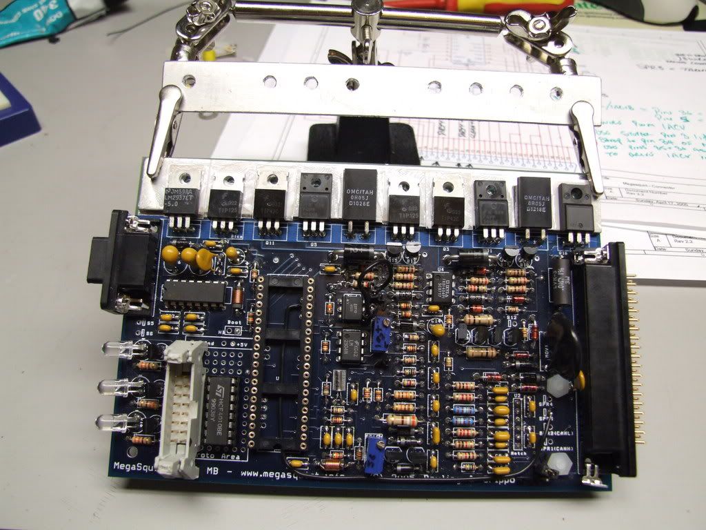
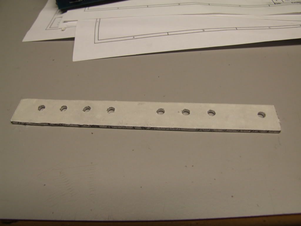
Image

Image

I used double sided tape on the underside for insulation and ease of fitting.

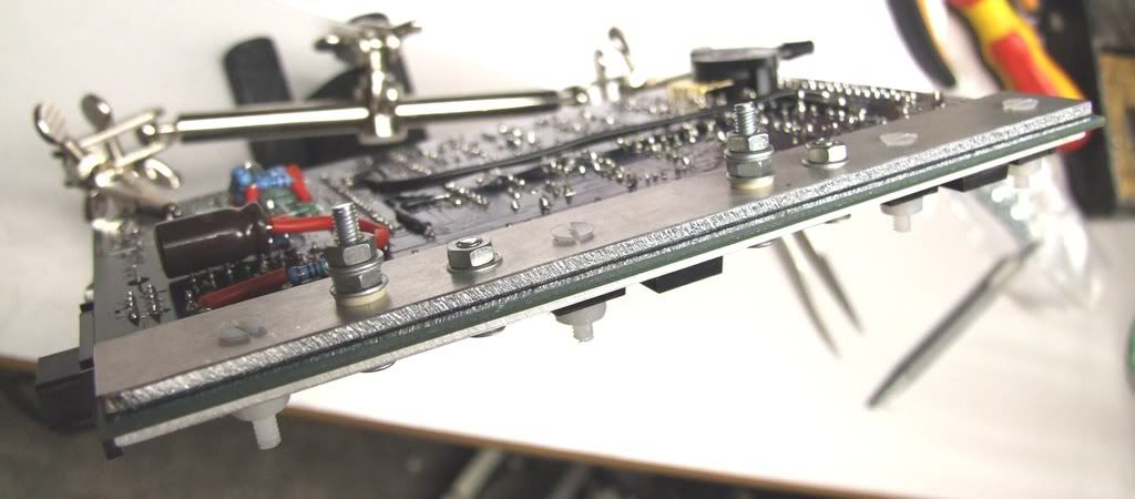
Next after sticking the new dirty bar to the PCB, i fitted the appropriate fixings to hold the power devices to the bars, you will notice in the shot below that I have 2 long bolts and 2 short bolts. Check these wont foul against the case as it is ground!!!
The 2 short bolts are connecting the Collector tabs of the TIP42 transistors to the new dirty ground bar. The 2 long screws are electrically connected to the collector tabs of the TIP125 transistors these should be isolated from both heatsink bars as these will be connected to the new dirty 12V supply.
it would be quite unwise to allow any shorts to ground here! make sure your holes are drilled cleanly and any swarf removed.

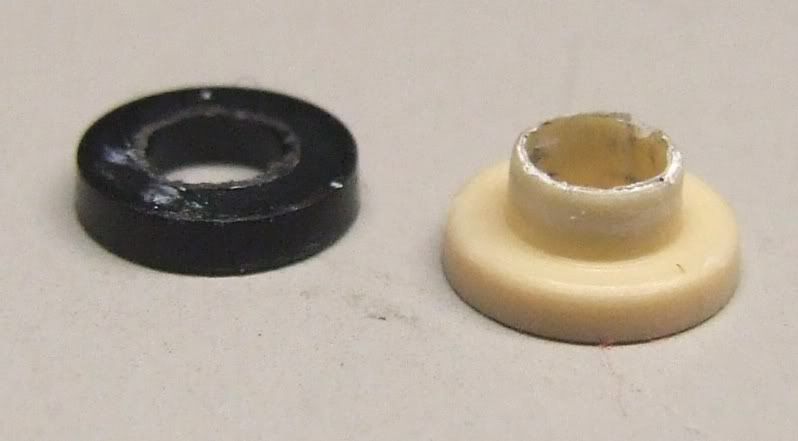
to properly insulate the screw from the new dirty bar, use insulating kits designed for TO220 devices but for the TIP125's you need to improvise a little.
Image

you need 2 insulating "tophat" washers per TIP125 screw, the first one (black in this shot) needs to be mutilated to make a sleeve for the threads as shown below.
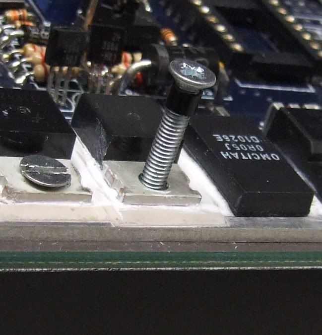
Image

Wind the screw all the way in (M3 are quite snug) and fit the other "tophat" to the under side between the dirty bar and the screw, hold that in place with a washer and nut and for the electrical connection to lug or bar use another 2 washers and a lock nut to clamp down, as shown below.
Image

Now you have all your new dirty connections solidly in place and waiting for heavy duty lugs, you can go about cutting the middle legs off the TIP42's and TIP125's also you want to cut the right legs of the current sense resistors. Do not cut the lead flush with the package, leave the thick section intact. once cut you can ether trim them flush with the PCB or remove them totally.

Image

now you have the problem that the ground side of the current sense resistors has nowhere to go so you fit a couple of links between the right pin of the resistors to the remaining stub of the TIP42 middle (collector) pins. This now takes the current flow to your dirty bar on the back of the board instead of the ground plane that is use by everything else.
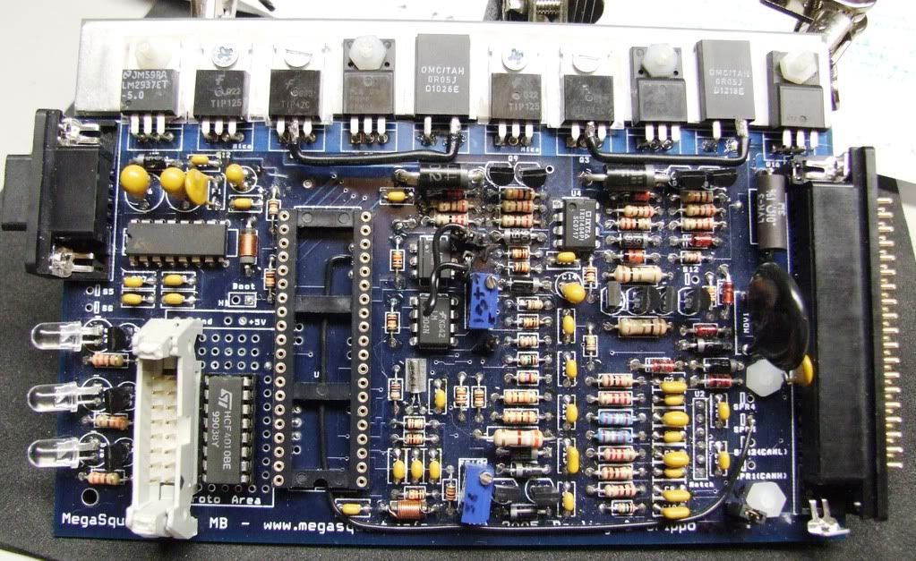
Image

As you can see there are 2 links fitted, I advise using insulated fairly thick wire as it carries up to 14 amps and runs under the CPU card (you don't want any shorting!)

Now on my setup I had strange injector behavior where every few seconds the injector pulse width would drop to virtually nothing and then begin to fire as normal. Using the real time display screen in megatune i could see the battery voltage fluctuating rapidly reaching 17 volts, it was when the voltage peaked that the injectors turned off briefly.
To filter out this crap i cut the track suppling VBatt to R3:
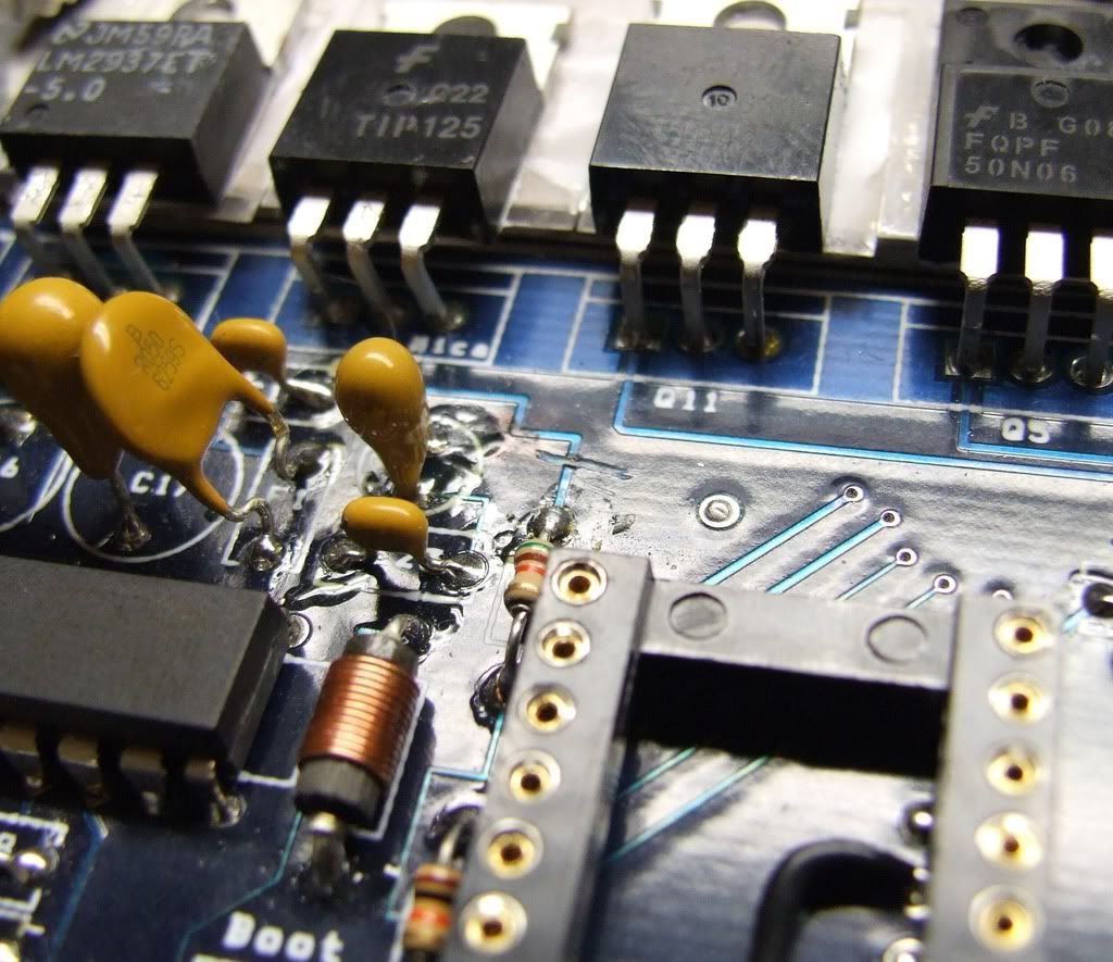
Image

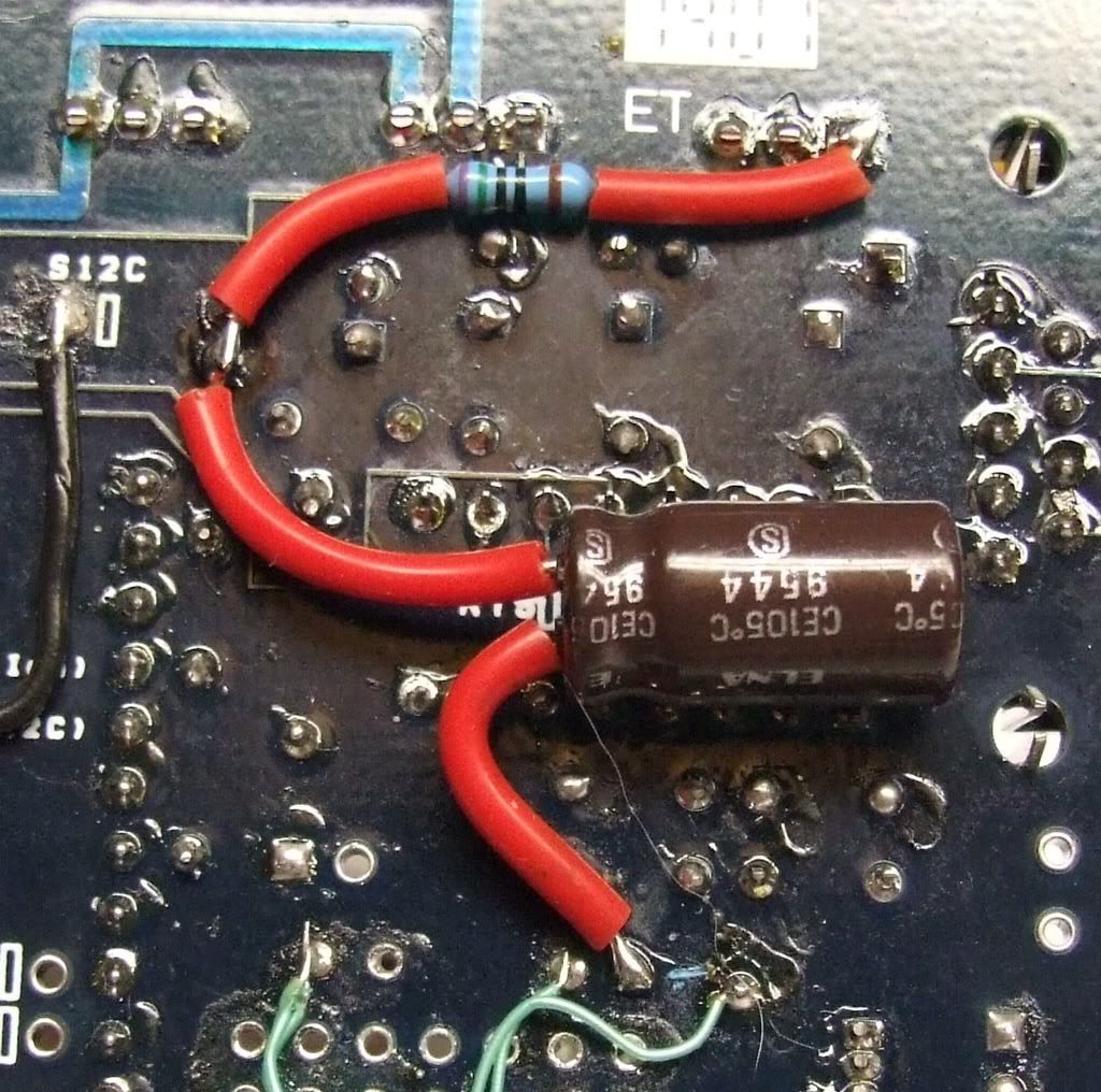
and put an RC filter using 750R and 220uF. The result is a minuscule voltage drop of 0.1V and it filters out anything above 1Hz at 6dB per oct, this will still allow compensation for electrical accessories turning on and off, but will stop erratic behavior.
All the components are mounted on the underside of the PCB, I get the 12V from pin 1 of U5 and the ground from the proto area. the connection in between the R and C is the topside of R3.

Don't be tempted to just put a big cap across the ADC input as it is used by the bootl oader on MS2 and will trigger it on bootup.
Image

Now as some of you may be aware I have a Bosch 3 wire PWM idle valve, this requires a push pull drive. I initially used 1 channel of the stepper motor chip on MS2 to provide this drive. after looking at the nasty crud coming back on the ground because of it. I have decided to put in a couple of mosfets on the new dirty bar to separate the noisy PWM valve and sink it back to dirty ground.

To get the PWM signal into the stepper chip I lifted Pin 3 and strapped it to pin 34 of the dip 40:
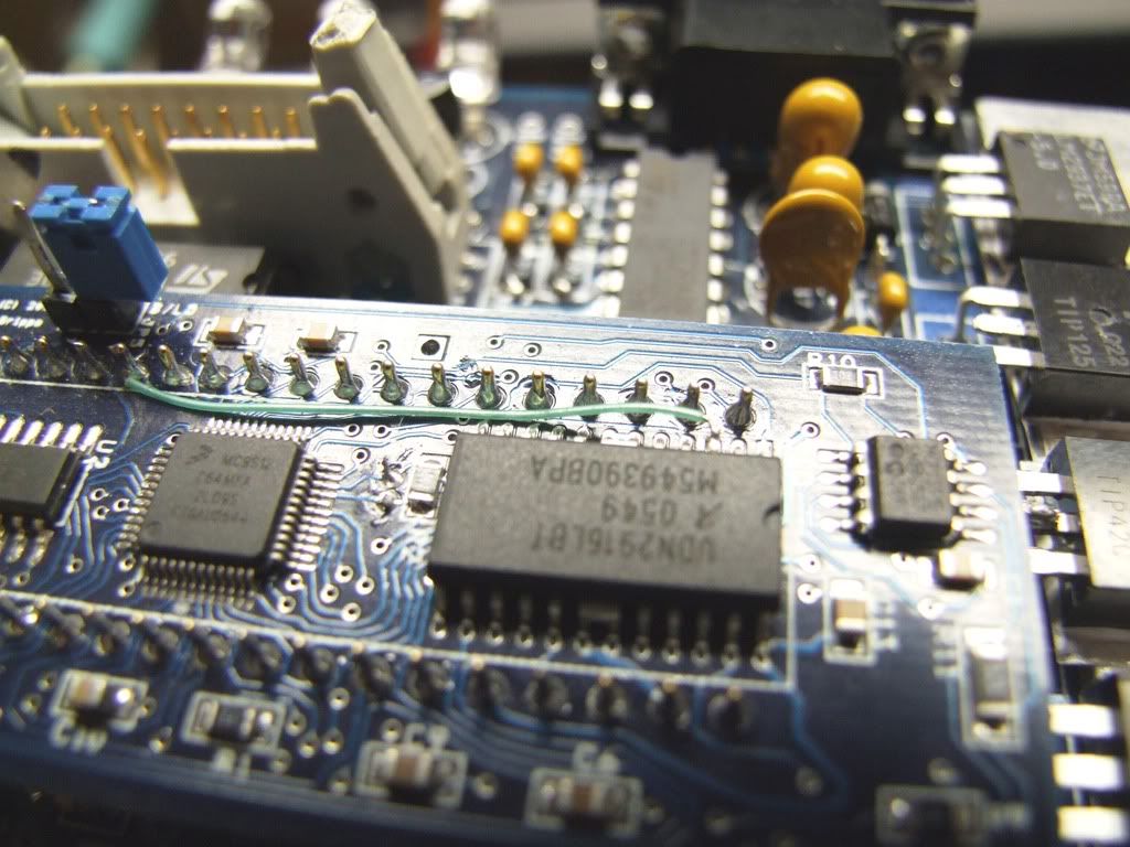
Image

the output of that 1 channel are naturally push pull, being lazy I just used those 2 outputs to drive the mosfets via a couple of 820R resistors (in the heatshrink tubing):
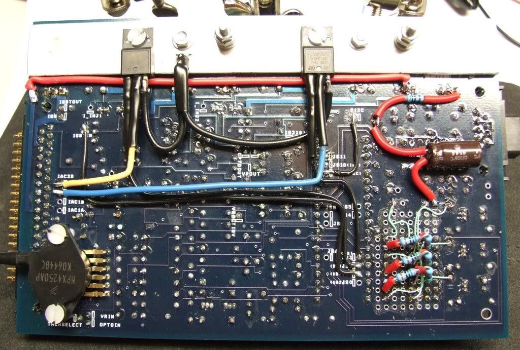
Image

You will notice a red wire running under the bar that is to beef up the supply to the sanctioned 12V it runs to the now unused TIP125 pad.

For the positive supply (overkill bar) i wanted to use this :P :
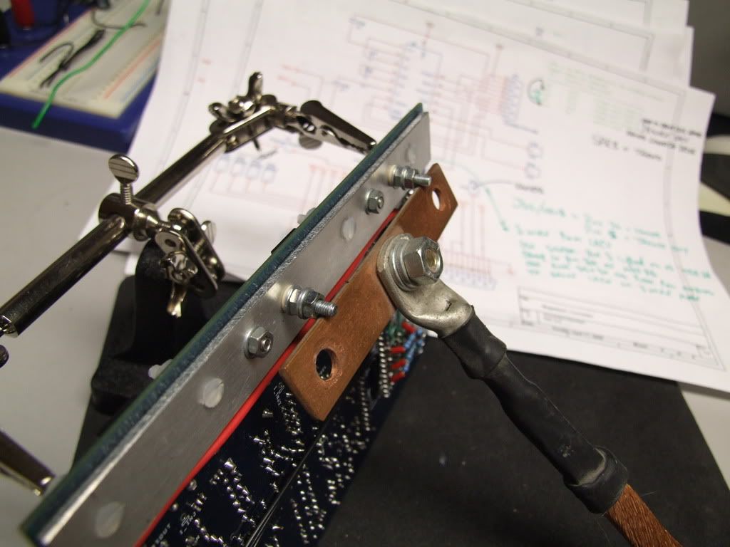
Image

but the actual power requirement here is very limited on Hi Z injectors, so i will use some modest sized lugs, that I will acquire from work tomorrow and post up some pics.

If you have any questions or have noticed something i may have missed please let me know, I have tested on the bench and it all works fine and it is electrically separated so in the car it should be hunky dory! ;)
93'BMW 325is M50B25TU, Rebuilt 06/06, JE10.5:1, polish&port. Scorpion BB, K&N CAI, TEJ21 WBO2, '07 M3 Evo 18" 225F, 255R, EBC Kevlar, Bilstien Sprint, Polyflex. Head rebuild Oct'08, OEM+FSE FPR, MS2v3.0_DJB Custom, Extra 2.0.1
User avatar
Fred
Moderator
Posts: 15431
Joined: Tue Jan 15, 2008 2:31 pm
Location: Home sweet home!
Contact:

Re: Separating the power and signal grounds on a V3 board

Post by Fred »

http://forums.hybridz.org/showthread.ph ... 713&page=5

Popular thread apparently :-)

Well done Dave and GearHead!

Fred.
DIYEFI.org - where Open Source means Open Source, and Free means Freedom
FreeEMS.org - the open source engine management system
FreeEMS dev diary and its comments thread and my turbo truck!
n00bs, do NOT PM or email tech questions! Use the forum!
The ever growing list of FreeEMS success stories!
gearhead
LQFP112 - Up with the play
Posts: 120
Joined: Sun Feb 03, 2008 9:30 pm
Location: Chicago, USA

Re: Separating the power and signal grounds on a V3 board

Post by gearhead »

what about the anodes of D6 and D20? Shouldn't these be pulled off the ground plane as well?

Also, if you do not install the current limiting stuff (Note 1 on the schematics) or the PWM stuff (Note 3), the modifications become even less complicated or invasive. You do not have R37 or R38, nor do you have Q9 or Q12 (the TIP125s). I do not install the current limiting stuff anyway to ensure rapid opening times nor the PWM stuff b/c I run HiZ injectors.

Gearhead
davebmw
LQFP144 - On Top Of The Game
Posts: 331
Joined: Sun Jul 13, 2008 2:58 pm
Location: South Wales, UK

Re: Separating the power and signal grounds on a V3 board

Post by davebmw »

gearhead wrote:what about the anodes of D6 and D20? Shouldn't these be pulled off the ground plane as well?

Also, if you do not install the current limiting stuff (Note 1 on the schematics) or the PWM stuff (Note 3), the modifications become even less complicated or invasive. You do not have R37 or R38, nor do you have Q9 or Q12 (the TIP125s). I do not install the current limiting stuff anyway to ensure rapid opening times nor the PWM stuff b/c I run HiZ injectors.

Gearhead

Not really necessary as they are for ground referencing only, the current path is through the transistor and down to the dirty ground.

This works perfectly even when driving Lo-Z injectors, the kick back used to produce up to 20 Volts on the same rail that is monitored for V Batt compensation! even worse because of the current flowing back through the standard ground system the ground on the board would float under load to 2 volts above actual battery -ve.

With the above modification/upgrade both digital and dirty grounds are solid and the battery monitoring is accurate to 0.3V, the chances of getting the MS2 working out of the box for the first time improve dramatically as you are just dealing with the variables you wan't not spurious noise.

So if you have a v3.00 PCB I highly recommend you separate your power rails, grounds and filter the V Batt monitor line, after all you want the damn thing to work for the £200/$400 you paid for it!
93'BMW 325is M50B25TU, Rebuilt 06/06, JE10.5:1, polish&port. Scorpion BB, K&N CAI, TEJ21 WBO2, '07 M3 Evo 18" 225F, 255R, EBC Kevlar, Bilstien Sprint, Polyflex. Head rebuild Oct'08, OEM+FSE FPR, MS2v3.0_DJB Custom, Extra 2.0.1
calkai
TO220 - Visibile
Posts: 7
Joined: Mon Nov 17, 2008 12:35 pm

Re: Separating the power and signal grounds on a V3 board

Post by calkai »

Hi,
Really really appreciate you hard work and sharing.
I am new in this forum, but have follow the above instruction to modify my V3 board.
What I discover is that if I attached the Battery Voltage sensing on pin1 of U5, the MS2 could be always frozen.
But If I attached it to the V12 directly, everything will be fine.
I have spent one day for checking any short or my chassis harness, nothing abnormal found.
davebmw
LQFP144 - On Top Of The Game
Posts: 331
Joined: Sun Jul 13, 2008 2:58 pm
Location: South Wales, UK

Re: Separating the power and signal grounds on a V3 board

Post by davebmw »

The V Ref line is normally connected to +12V via a potential divider 50K on the top and 10K on the lower half.
all i have done is use a resistor in line and a cap to smooth the fluctuations the output of which connects to the 50K of the potential divider.
Are you talking about connecting the MCU pin directly to U5 pin1?
93'BMW 325is M50B25TU, Rebuilt 06/06, JE10.5:1, polish&port. Scorpion BB, K&N CAI, TEJ21 WBO2, '07 M3 Evo 18" 225F, 255R, EBC Kevlar, Bilstien Sprint, Polyflex. Head rebuild Oct'08, OEM+FSE FPR, MS2v3.0_DJB Custom, Extra 2.0.1
calkai
TO220 - Visibile
Posts: 7
Joined: Mon Nov 17, 2008 12:35 pm

Re: Separating the power and signal grounds on a V3 board

Post by calkai »

Find out the real root of my fault.
The connection is exactly right.
The reason of MS-II frozen is that :
I set up. 1 squirt per cycle, 1 cylinder, and then chose Missing Tooth Trigger.
The equation on the MS-II code will have problem in calculation.
davebmw
LQFP144 - On Top Of The Game
Posts: 331
Joined: Sun Jul 13, 2008 2:58 pm
Location: South Wales, UK

Re: Separating the power and signal grounds on a V3 board

Post by davebmw »

calkai wrote:Find out the real root of my fault.
The connection is exactly right.
The reason of MS-II frozen is that :
I set up. 1 squirt per cycle, 1 cylinder, and then chose Missing Tooth Trigger.
The equation on the MS-II code will have problem in calculation.
Ahhhh! now I understand. :)
So you aren't having difficulty running with my modification on your V3 PCB and the problems you are seeing, are related to software/configuration settings.

Thats good I was getting worried there for a second :lol2: I found that after the mods the noise detected by the MCU was reduced from several volts of noise to a couple of mV. The difference to the ease of setup and tuning was well worth the work.
93'BMW 325is M50B25TU, Rebuilt 06/06, JE10.5:1, polish&port. Scorpion BB, K&N CAI, TEJ21 WBO2, '07 M3 Evo 18" 225F, 255R, EBC Kevlar, Bilstien Sprint, Polyflex. Head rebuild Oct'08, OEM+FSE FPR, MS2v3.0_DJB Custom, Extra 2.0.1
calkai
TO220 - Visibile
Posts: 7
Joined: Mon Nov 17, 2008 12:35 pm

Re: Separating the power and signal grounds on a V3 board

Post by calkai »

Need to discuss one point about Battery Voltage Sensing.

In the above photo, the Battery Vol Sensing circuit is attached on the input of U5, but at this point the voltage had been regulated by before circuit, right?

May the Battery Voltage not be correctly reflected?

Would the injector and ignition be affected?
gearhead
LQFP112 - Up with the play
Posts: 120
Joined: Sun Feb 03, 2008 9:30 pm
Location: Chicago, USA

Re: Separating the power and signal grounds on a V3 board

Post by gearhead »

Group,

I have just finished a similar modification. When I build a V3 board, I do not install the current limiting nor the PWM circuitry, so this modification to take to power ground off the board is simplified substantially. I use a PWM valve and needed to take this to the power ground as well. I will document and photo my board in my next post. Another thing to consider is that all outputs should have a ground separate from the inputs. This goes for the spark outputs as well. To do this requires pulling the top leg of the LED drive transistors and routing it to the power ground as well. Ideally, this sould be a separate ground from the injection power gnd, but it should be kept off the signal ground (inputs).

Gearhead
Post Reply