Re: Separating the power and signal grounds on a V3 board
Posted: Mon Aug 25, 2008 11:32 am
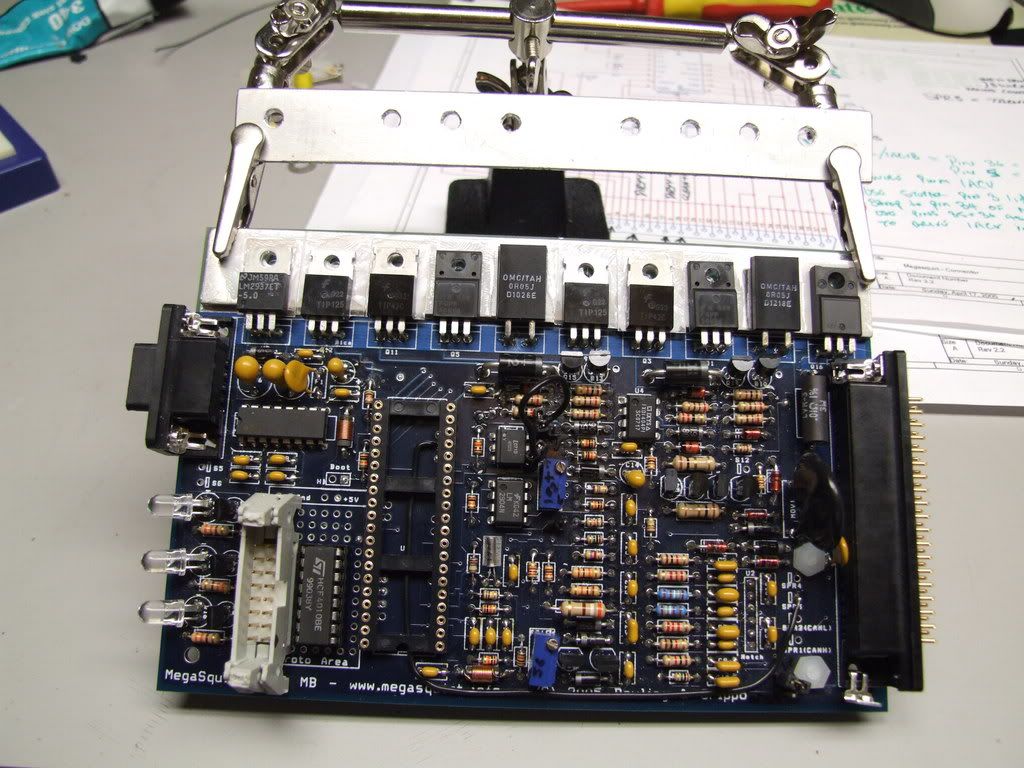
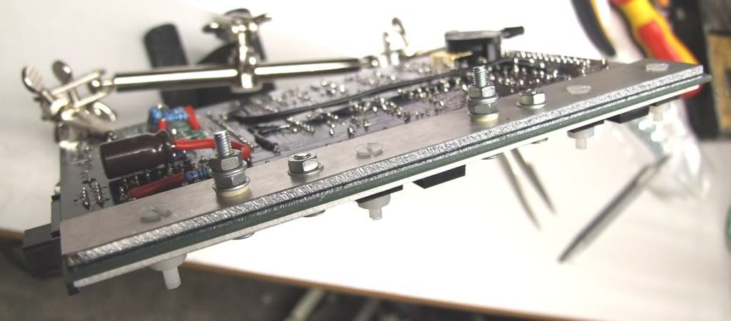
it may also be worth noting that the regulator U5 is bolted to the heatsink bar and requires insulating with a mica pad.
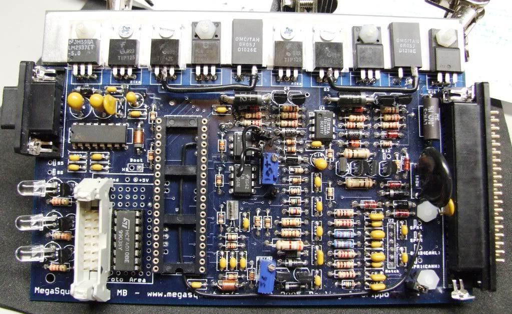
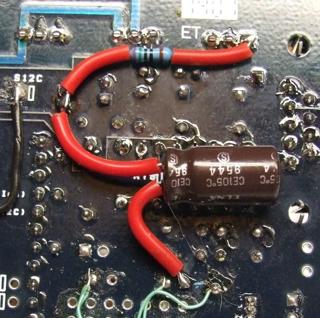
The battery voltage input to AD4-1 is taken directly from the collector of Q12 which introduces loads of unwanted noise even when not using the PWM mode, i dread to think what its like with Lo-Z injectors.
I rigged up a filter for the battery voltage reference as you don't need it to measure the noise, a 220uF cap from ground to the V12 side of R3 will smooth the input but for extra filtering cut the track from R3 to Q12 collector and place a 750R resistor from pin 1 of U5 to this new cap. This will make a low pass RC filter with a 6dB/oct above 1Hz.
Accessories switching on in the car with a low enough impedance to have any effect on Vbatt will still be compensated for but the spurious switching noise will be gone.
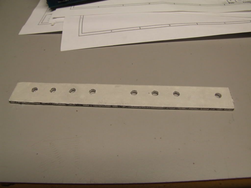
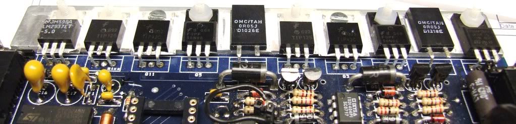
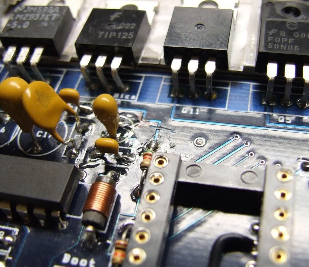
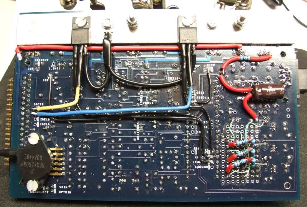
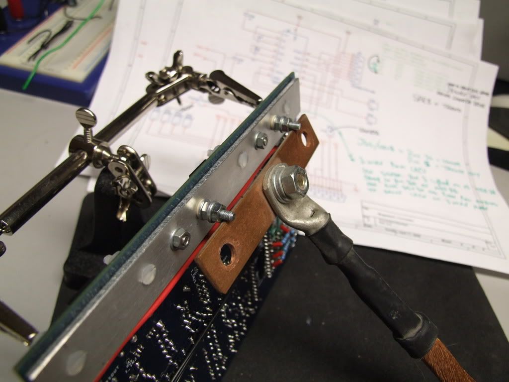
the heatsink bar is grounded by the main ground plane, I'm looking at insulating all the TO220 tabs, cutting the spider tracks to the grounded side of R37 & 38, cutting off the middle legs (collectors) on Q3 & 11 and using the tabs to connect to a second ground bar running on the underside.
This can then be connected via a very thick cable to a proper chassis earth.
Making sure obviously to ensure that Q9 & 12 are properly isolated as the tabs of these are connected to 12V.
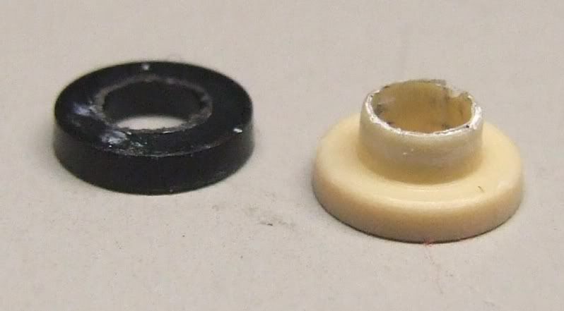
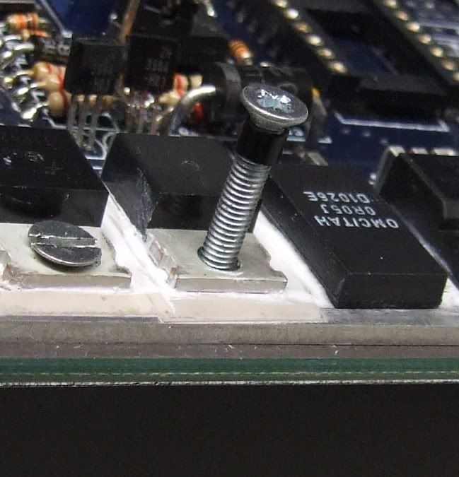
I will need to ensure that the bolts connecting the tabs to the new ground bar are insulated from the top bar and the through plated holes in the PCB.
the ground sides of R37 & 38 will be reconnected to the new dirty bar either by wire and tags or if i can find that nice copper bar I had around here I may solder them.
will post pics soon.
The battery voltage input to AD4-1 is taken directly from the collector of Q12 which introduces loads of unwanted noise even when not using the PWM mode, i dread to think what its like with Lo-Z injectors.
I rigged up a filter for the battery voltage reference as you don't need it to measure the noise, a 220uF cap from ground to the V12 side of R3 will smooth the input but for extra filtering cut the track from R3 to Q12 collector and place a 750R resistor from pin 1 of U5 to this new cap. This will make a low pass RC filter with a 6dB/oct above 1Hz.
Accessories switching on in the car with a low enough impedance to have any effect on Vbatt will still be compensated for but the spurious switching noise will be gone.
the heatsink bar is grounded by the main ground plane, I'm looking at insulating all the TO220 tabs, cutting the spider tracks to the grounded side of R37 & 38, cutting off the middle legs (collectors) on Q3 & 11 and using the tabs to connect to a second ground bar running on the underside.
This can then be connected via a very thick cable to a proper chassis earth.
Making sure obviously to ensure that Q9 & 12 are properly isolated as the tabs of these are connected to 12V.
I will need to ensure that the bolts connecting the tabs to the new ground bar are insulated from the top bar and the through plated holes in the PCB.
the ground sides of R37 & 38 will be reconnected to the new dirty bar either by wire and tags or if i can find that nice copper bar I had around here I may solder them.
will post pics soon.