OK as Fred requested I have come up with a master plan to get all of the dirty noisy crap off of the power rails used by the MCU and sensitive stuff.
so here goes....
First we need to split off the high power ground return and provide another way for the injector low side mosfets to get the current back to ground.
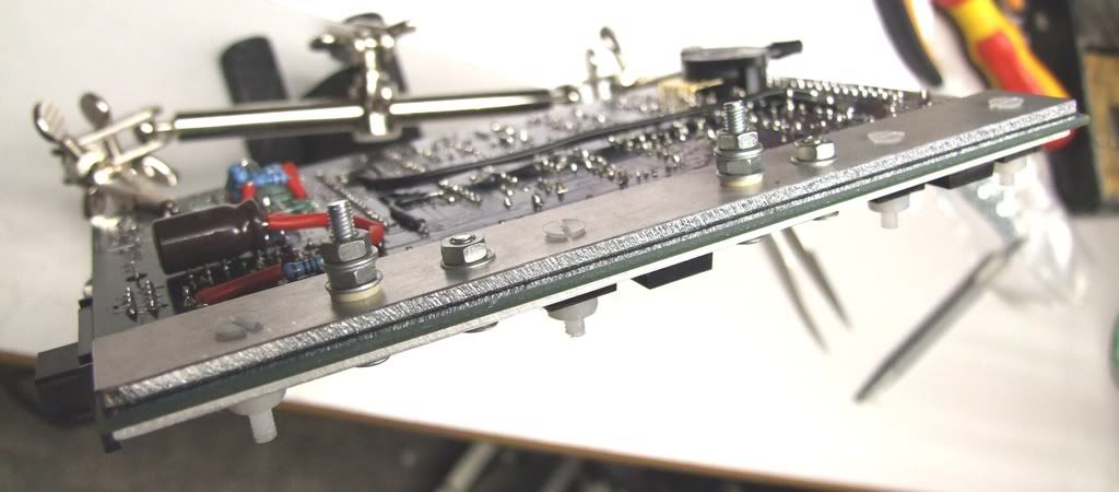
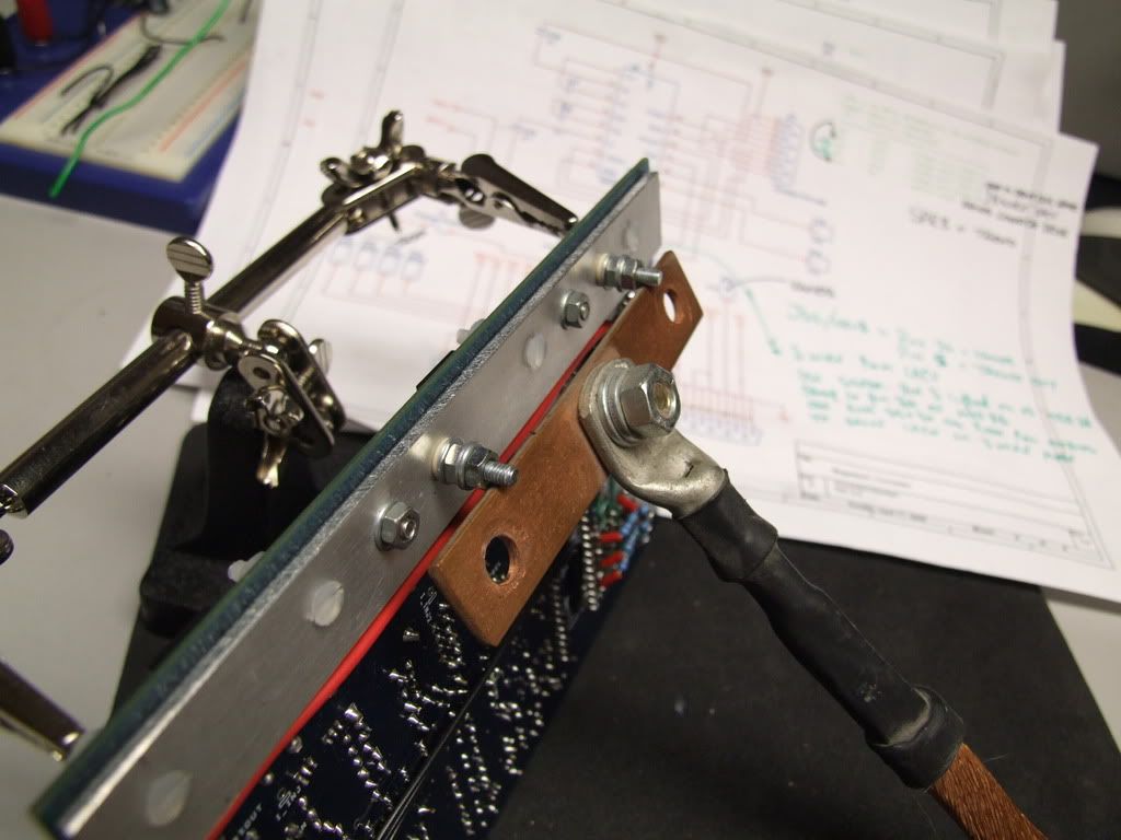
to do this i chose to make a second heatsink bar on the back and strap it via very thick cables back to a solid chassis earth or preferably the battery.
so I got out my trusty plasma cutter (hacksaw will do) and pretty much duplicated the top bar only using slightly thicker ally (3mm).
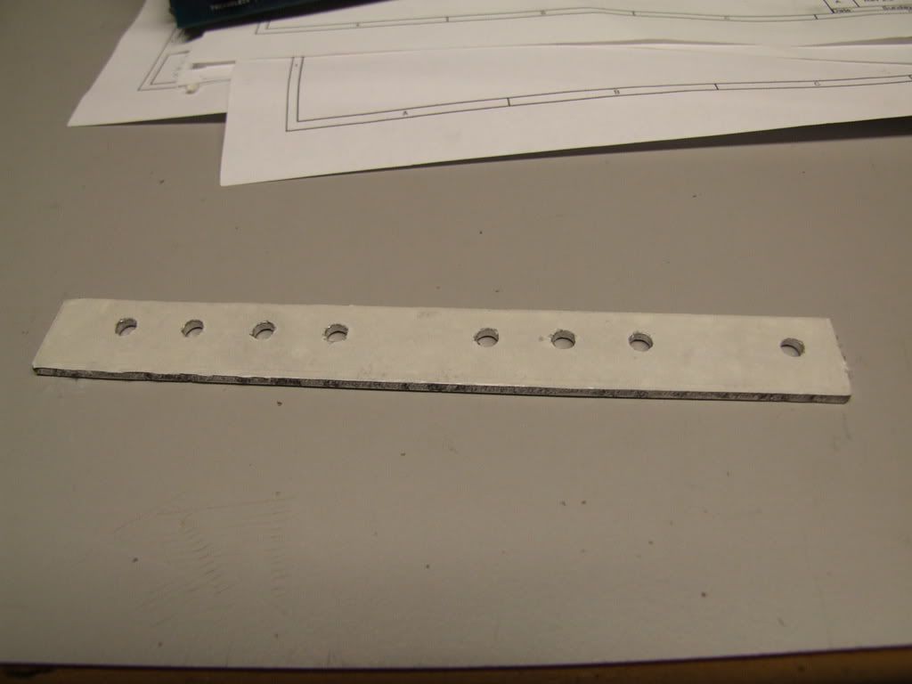
I used double sided tape on the underside for insulation and ease of fitting.
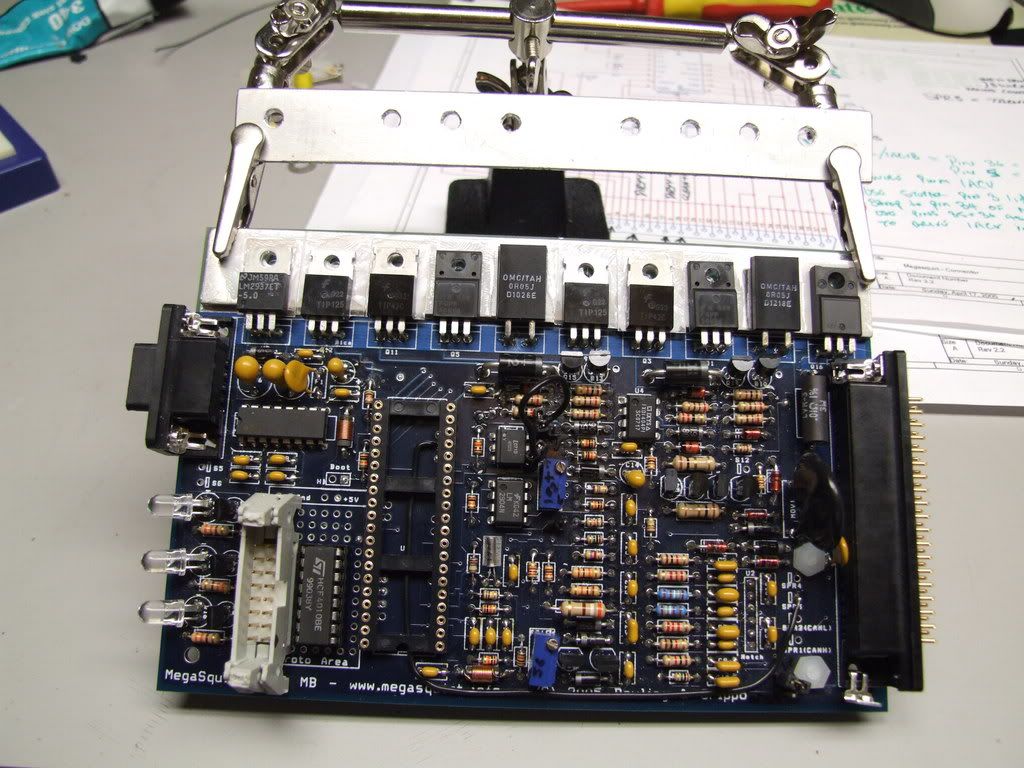
Next after sticking the new dirty bar to the PCB, i fitted the appropriate fixings to hold the power devices to the bars, you will notice in the shot below that I have 2 long bolts and 2 short bolts. Check these wont foul against the case as it is ground!!!
The 2 short bolts are connecting the Collector tabs of the TIP42 transistors to the new dirty ground bar. The 2 long screws are electrically connected to the collector tabs of the TIP125 transistors these should be isolated from both heatsink bars as these will be connected to the new dirty 12V supply.
it would be quite unwise to allow any shorts to ground here! make sure your holes are drilled cleanly and any swarf removed.
to properly insulate the screw from the new dirty bar, use insulating kits designed for TO220 devices but for the TIP125's you need to improvise a little.
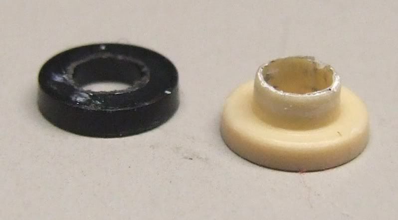
you need 2 insulating "tophat" washers per TIP125 screw, the first one (black in this shot) needs to be mutilated to make a sleeve for the threads as shown below.
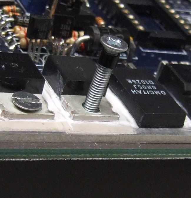
Wind the screw all the way in (M3 are quite snug) and fit the other "tophat" to the under side between the dirty bar and the screw, hold that in place with a washer and nut and for the electrical connection to lug or bar use another 2 washers and a lock nut to clamp down, as shown below.
Now you have all your new dirty connections solidly in place and waiting for heavy duty lugs, you can go about cutting the middle legs off the TIP42's and TIP125's also you want to cut the right legs of the current sense resistors. Do not cut the lead flush with the package, leave the thick section intact. once cut you can ether trim them flush with the PCB or remove them totally.
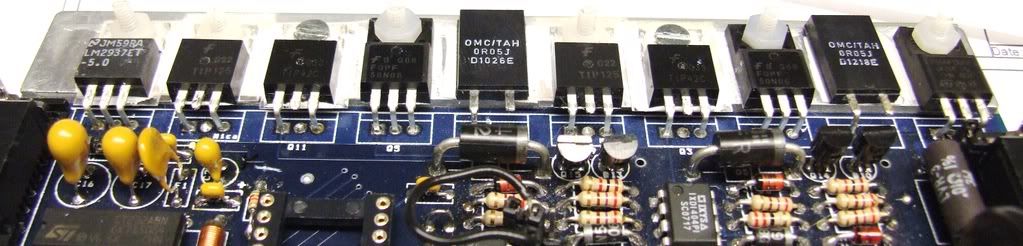
now you have the problem that the ground side of the current sense resistors has nowhere to go so you fit a couple of links between the right pin of the resistors to the remaining stub of the TIP42 middle (collector) pins. This now takes the current flow to your dirty bar on the back of the board instead of the ground plane that is use by everything else.
As you can see there are 2 links fitted, I advise using insulated fairly thick wire as it carries up to 14 amps and runs under the CPU card (you don't want any shorting!)
Now on my setup I had strange injector behavior where every few seconds the injector pulse width would drop to virtually nothing and then begin to fire as normal. Using the real time display screen in megatune i could see the battery voltage fluctuating rapidly reaching 17 volts, it was when the voltage peaked that the injectors turned off briefly.
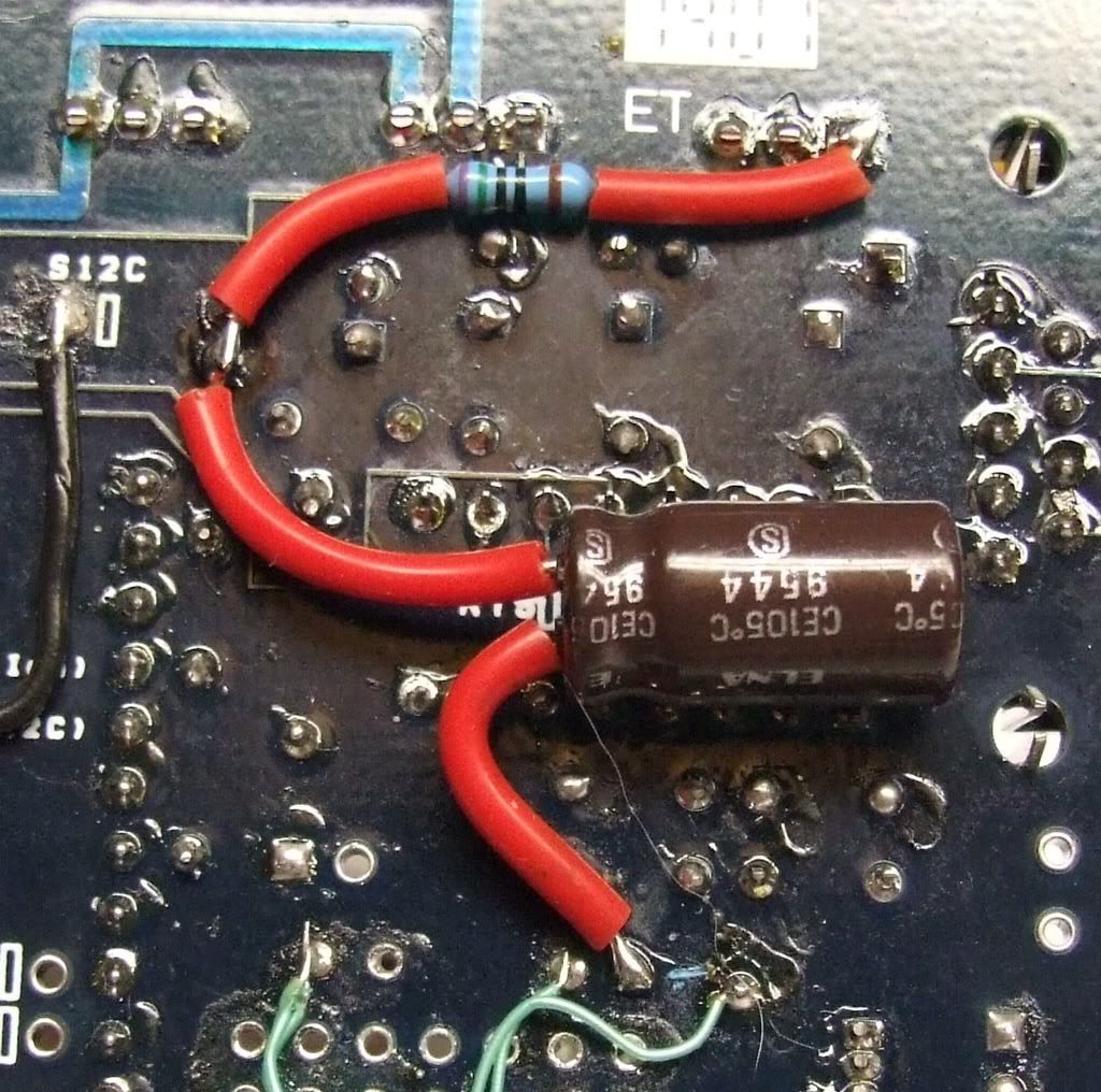
To filter out this crap i cut the track suppling VBatt to R3:
and put an RC filter using 750R and 220uF. The result is a minuscule voltage drop of 0.1V and it filters out anything above 1Hz at 6dB per oct, this will still allow compensation for electrical accessories turning on and off, but will stop erratic behavior.
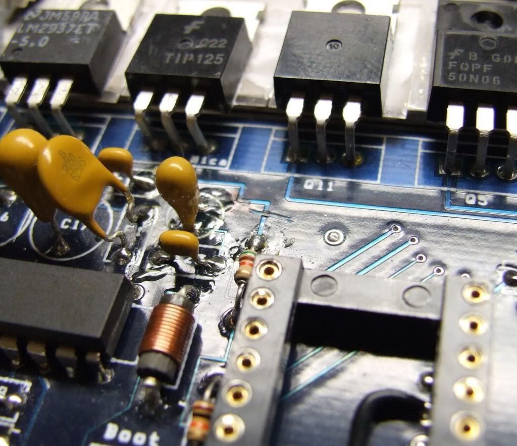
All the components are mounted on the underside of the PCB, I get the 12V from pin 1 of U5 and the ground from the proto area. the connection in between the R and C is the topside of R3.
Don't be tempted to just put a big cap across the ADC input as it is used by the bootl oader on MS2 and will trigger it on bootup.
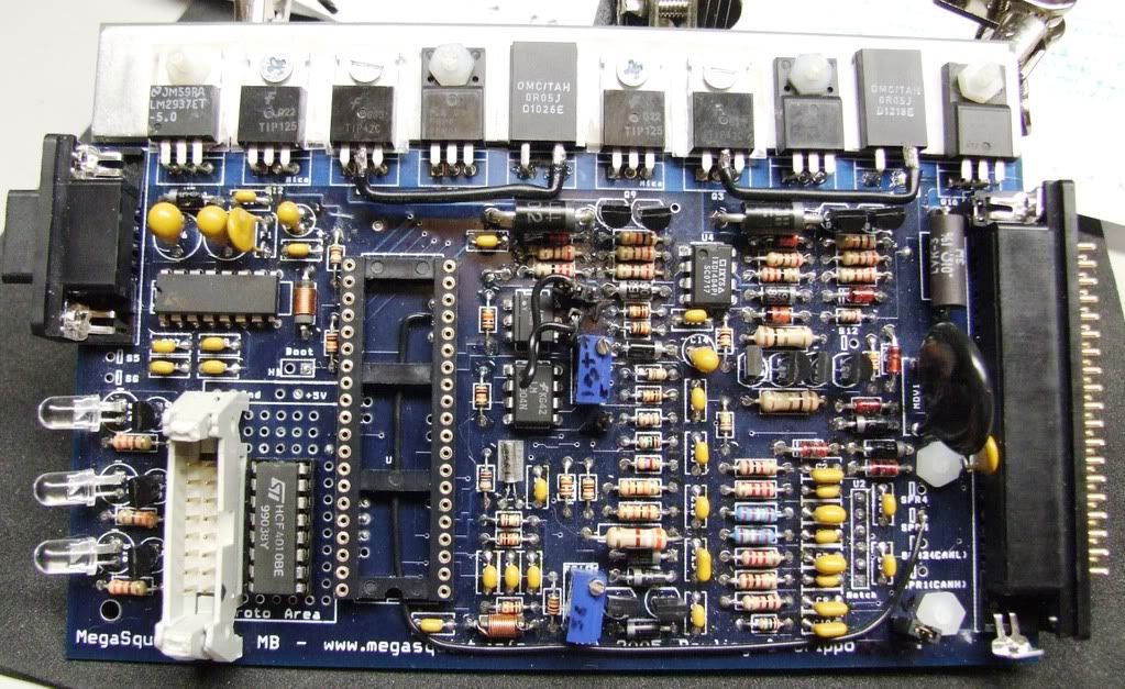
Now as some of you may be aware I have a Bosch 3 wire PWM idle valve, this requires a push pull drive. I initially used 1 channel of the stepper motor chip on MS2 to provide this drive. after looking at the nasty crud coming back on the ground because of it. I have decided to put in a couple of mosfets on the new dirty bar to separate the noisy PWM valve and sink it back to dirty ground.
To get the PWM signal into the stepper chip I lifted Pin 3 and strapped it to pin 34 of the dip 40:
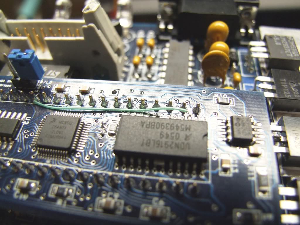
the output of that 1 channel are naturally push pull, being lazy I just used those 2 outputs to drive the mosfets via a couple of 820R resistors (in the heatshrink tubing):
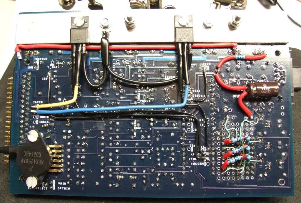
You will notice a red wire running under the bar that is to beef up the supply to the sanctioned 12V it runs to the now unused TIP125 pad.
For the positive supply (overkill bar) i wanted to use this

:
but the actual power requirement here is very limited on Hi Z injectors, so i will use some modest sized lugs, that I will acquire from work tomorrow and post up some pics.
If you have any questions or have noticed something i may have missed please let me know, I have tested on the bench and it all works fine and it is electrically separated so in the car it should be hunky dory!

