Here are some examples :
Skyline/RBXX(D)E(T) :
This text pinched from one of our members posts on another board :
I hope that helps you with your efforts Sean, I'd love to see that working. It would make FreeEMS THE choice for Nissan enthusiasts :-)510rob wrote:* The outer 1° sensor(s), with three aperture slots, must contain multiple (perhaps three?) opto pickups, and must be connected to some type of sequential detector block; the opto behavior is not at all what I'd expect to see from a simple opto-sensor being interrupted with a piece of paper; it seems to require a properly sequential change on each consecutive aperture slot in order to register a valid edge-trigger signal. The sensor works as an "opto" only when the wheel is turning as it would in normal operation. Mitsubishi may have done this to eliminate false timing signals at low speeds/cranking ???
* The inner "120°" sensor is a typical binary sensor.
* Both outputs need pull-up resistors.
I stumbled across an interesting description of the CAS timing scheme...
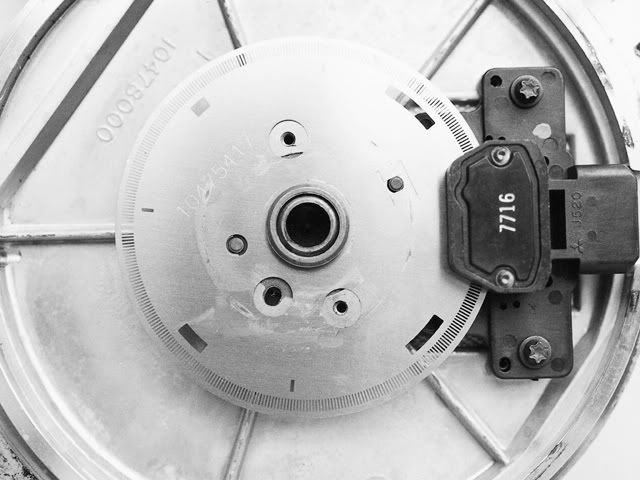
If you have a look at the pic of the Rb25 CAS you will see the slots on the outside of the disk are at 1 deg spacing and the inside of the disk the 6 slots are of vairing size starting at TDC for each piston. There are 4deg difference in each slot with the first slot 4 deg wide and the last 24deg wide. The divider simply counts the number of degrees using the 1deg signal while the 60deg signal is low (while there is metal between the sensor, not slot). The results are in binary
36 = 100100, 40 = 101000, 44 = 101100, 48 = 110000, 52 = 110100, 56 = 111000
If you only read the middle digits, take the 1 off the front and the 00 off the end your left with
001 = 1, 010 = 2, 011 = 3, 100 = 4, 101 = 5, 110 = 6
These 3 digits are latched and feed through a binary to 1-of-6 decoder. The outputs from the decoder are on for 120deg of each cycs compression stroke up to TDC and is conected to the base of 6 NPN transistors. The colectors of the transistors are conected the the ignition signal from the ECU and the emitters conected to the RB25 coil driver pack, 1 for each coil. The ign sig from the ECU only gets to the coil to be fired and is blocked to all the others by the transistors.
I also convert the 60deg signal from wide slots to narrow slots so the RB30E ECU thinks its got a RB30 CAS.
http://www.calaisturbo.com.au/printthre ... ge=2&pp=40
Admin.