These are the CNG injectors I used
http://www.europegas.pl/documents/VALTEK_tech_spec.pdf
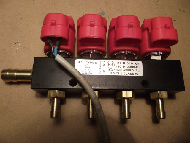
Briefly: 3ohm,4.5msec to reach peak current given its inductance/mass, 3.3msec opening time.
The board is an SMD version of the P&H driver, except for the driver itself that doesn't come in SMD fashion.
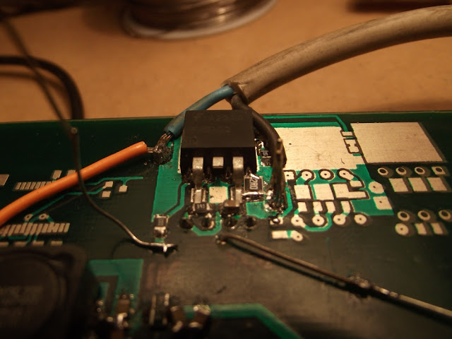

The green cable is in there because the mfg can't do a damn via or a decent soldermask, and the 2ohm resistor footprint should be a bit bigger.
This is the setup almost ready to test, My power supply can't deliver more than 3Amps or so, so the testing needed a proper battery.

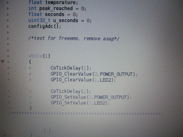
You can see an mbed board, its an ARM Cortex M3 microcontroller running at 100MHz, programmed with gcc+CoOS, a very nice open source rtos for ARM. It is in charge of generating the pulses to drive the injector.
An mbed is usually powered up from a PC USB, but in this case its supplied from the SMPS that was under testing for puma spin2. SMPS is on the left making 6v, linear regs are on the right, mbed takes its power (5v) from the small, non-shutdownable reg.
Its sad that this is the best pcb quality I can find in nearly 700km. Check the pads and holes out of center, and the mask 1mm away from where it should be at the right. Its enough for a test like this one anyway.
Here is a video of the first test I made in linear mode. It wasn't too hot, really. But doing a harder test in the lab with a resistor as a charge it did get hot, barely touchable. Btw, last night it was -1°C in the garage, so temperature isn't a good parameter in there,
http://www.youtube.com/watch?v=eJlPsVoPHlg
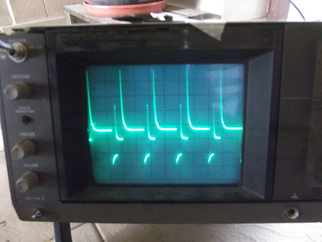
The actual behavior looks like this

Note that hold current is 1A, and peak should be close to 4A, and is not.
You can see Vce Saturation voltage is high, I'm going to try with the original darlington to see if thats why I have such a small current in there. Maybe the driver should flow more current to drive this transistor, could be a dumb mistake too.
This is the transistor used
http://www.fairchildsemi.com/ds/FJ/FJB102.pdf
These are suggested by the driver
Linear mode:
http://www.kekew.net/upfile/pdf/2N6045.pdf
PWM mode:
http://www.fairchildsemi.com/ds/TI/TIP120.pdf
And the main thing, I still have to test it in PWM mode. I had a short under the chip because of not having soldermask (I explicitly asked 'no soldermask in the bottom, and don't do any hole to the board'), lets hope its was not catastrophic. I have spare components anyway.
That will happen later, I'm loaded with homework.