Page 1 of 3
Coil regulation related schematic diagrams and issues
Posted: Sat May 07, 2011 2:58 pm
by STC
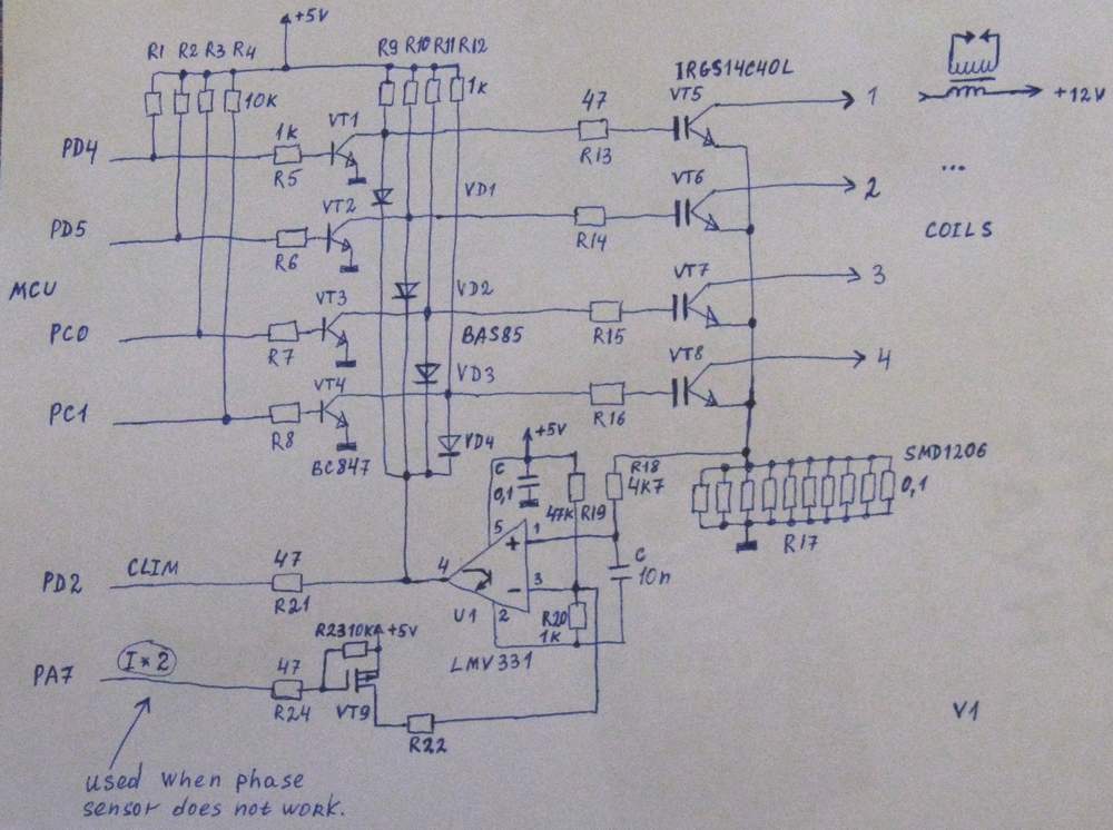
I've started to develop new version of hardware named SECU-3E (Enhanced) and looking for good solution to build simple and reliable igniter. Currently SECU-3 has no "on board" power outputs to directly drive coils.
Requirements:
- simple;
- using IGBT or FET;
- current limiting abilities;
I've already developed some schematic diagram. Can you give some comments and suggestions about mentioned schematic diagram?
p.s.
- Inputs of U1 must be swapped (my mistake)
- I*2 used to increase threshold of comparator because when phase sensor does not work, IGBTs will work in pairs.
- R22 is 47k
Re: Coil regulation related schematic diagrams and issues
Posted: Tue May 31, 2011 2:12 pm
by STC
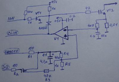
I think it is necessary to add some little positive feedback to U1 comparator.
Re: Coil regulation related schematic diagrams and issues
Posted: Tue May 31, 2011 2:17 pm
by STC
Also, I have some ideas how to implement soft cutoff
Re: Coil regulation related schematic diagrams and issues
Posted: Tue May 31, 2011 4:49 pm
by Fred
STC, you can't use a single comparator to do current limiting like that as the dwells will naturally overlap sometimes and cause false limiting, not good. This becomes true at high RPM in wasted spark mode, or with aggressive dwell in other modes. Low battery voltage will cause this requirement too. If you swap to a part designed for this purpose, you'll get built in per device current limiting. I'd suggest doing that.
www.octopart.com
Secondly, you're much better off not having this stuff on the board anyway. Junk yard ignitors are so cheap and easy to find, it makes no sense to do anything else.
Thirdly, if you go ahead and do this anyway, make sure your grounds are isolated such that you don't ruin all of your sensor readings with ign coupled noise.
Fourth, are you sure that you want to put 10 1206 smd resistors on the board to take the place of a single 0.01 power resistor? Especially as if you do what you're planning you've got 40 of them to include.
Enjoy!
Fred.
Re: Coil regulation related schematic diagrams and issues
Posted: Tue May 31, 2011 10:55 pm
by STC
Thank you!
1. Ok. I already thought about this. But you are right about overlapping of accumulation phases and it is bad idea do not allow dwells to overlap (bad limitation, especially on hardware level).
Then, I will look at quad operational amplifiers (like LM2902 etc)
2. Yes, I agree with you. Moreover, current versions of hardware are intended for using of external ignitors. But it is convenient for some users to deal with single "box" only

(e.g. easy to mount).
3. I am going to use separate grounds (separate pins on the external connector) and special pcb layout.
4.
40 SMD resistors are nightmare, really. So, I have to use monolithic 2-5W resistors.
Re: Coil regulation related schematic diagrams and issues
Posted: Tue May 31, 2011 11:01 pm
by STC
I've found nice IC for such purpose, but it is too expensive and hard to acquire.
http://www.onsemi.com/pub/Collateral/CS8312-D.PDF
Re: Coil regulation related schematic diagrams and issues
Posted: Wed Jun 01, 2011 7:41 am
by Fred
STC, all of the special purpose ignition drivers (which are common and cheap enough) have current limiting built in, why not use those and forget about your special circuit? Then all you need to do is buffer the current to the gate of them, easy.
Re: Coil regulation related schematic diagrams and issues
Posted: Wed Jun 01, 2011 11:29 am
by STC
What do you mean by "ignition drivers"? Do you mean special IC with integrated powerful transistor and control logic? Or, it can be monolithic unit with integrated powerful transistor, control logic and coil.
Re: Coil regulation related schematic diagrams and issues
Posted: Wed Jun 01, 2011 9:36 pm
by Fred
http://octopart.com/partsearch/#search/ ... ion%20igbt
http://datasheet.octopart.com/IRGS14C40 ... 550209.pdf
or
BIP373
or
http://datasheet.octopart.com/NGP15N41C ... 156439.pdf
etc. Maybe not all do have current limits, but you also don't want current limits, really, you want the device to not fail, and you want the coil to get max current asap. only under a fault condition do you want current limiting, and the only upside to it is that it recovers when the fault is removed, the downside being that you need to handle potentially MASSIVE heat coming from the device.
Food for thought!
Fred.
Re: Coil regulation related schematic diagrams and issues
Posted: Thu Jun 02, 2011 9:42 am
by STC
Thank you for some links!
I really need current limiting, because system must be reliable. Lets imagine following situation. User can edit lookup table related to accumulation time. If he set wrong values (too long accumulation time), transistors can burn. Another example. Firmware can be damaged (e.g. user interrupts firmware downloading). In this case firmware may work in wrong (unsafe) way, which also may lead to burning of transistors.