Page 5 of 5
Re: Another MAX9926 VR board
Posted: Fri Jul 29, 2016 10:00 pm
by ehb
Hey Ivan,
great work, both the board and the reflow oven. I'm not sure what sensor I'll receive, but I might need a board some time too.
If it is indeed a big hassle for you to come up with a testing rig, I could easily build something with ball bearings to mount the wheel on. Shipping from Germany is 9€ though and I'm a cheap bastard.

If you have an air compressor, high speeds are possible.
Time is thin though, but I guess I could squeeze that in. If others could measure other typical diameters of various trigger wheels, we could come up with a simple pyramid shaped turned part with two ball bearings beneath. Just an idea - would make a one-off for your wheel too.
Re: Another MAX9926 VR board
Posted: Fri Jul 29, 2016 11:06 pm
by Fred
Glad you noticed that! Was the first thing I saw. :-) Cough, 115VAC, cough.
EDIT: didn't see ehb's post, compressed air is a great idea, or even water jet if your rig is IP65 LOL :-)
Re: Another MAX9926 VR board
Posted: Sat Jul 30, 2016 12:10 pm
by ivan141
Fred, you're just one of those people that like to watch the world burn

115VAC All the things!
Dont really see the point, my sensor operates primarily between 0.2V - 2V.
Re: Another MAX9926 VR board
Posted: Sat Jul 30, 2016 12:20 pm
by Fred
I don't know what world you're living in, possibly below sea level where the salt water shorts out the signal? Oh, you actually are! But it's dry there, I've been there :-)
2V is not even close to true. This is why the max requires excellent decoupling and 10k input resistors: It's designed to take a high voltage beating and anything with a close tolerance sensor that spins decent RPMs will create upwards of 50V AC. This is why. 60-2 users who rev to 8k + are highly likely to test these limits.
Is 50 or 60 Hz sine wave a fair test in terms of energy density? Likely not, likely a bit heavier test than the real wave form shape, but it's close. If your resistors are appropriately rated, 115V AC should be cake for them. Make sure you don't have the shunt in there at the time, though :-D
Re: Another MAX9926 VR board
Posted: Mon Mar 09, 2020 9:08 am
by Tobbera
Hi all. I'm new in this board. I saw this thread and undertand there is a fair bit of VR vs MX9926 knowledge on here.
I reaching out to you for advise on my setup.
The circuit is as bellow. The wheel has two teeth, one lone and one short. I would like to detect those, but most of what i get is just noise. My reading and reaserach has led me to think that the gap between the edges are so far apart, and the wheel is rotating so slow, that the watchdog in the MAX9926 is resetting. Any ideas?
Circuit
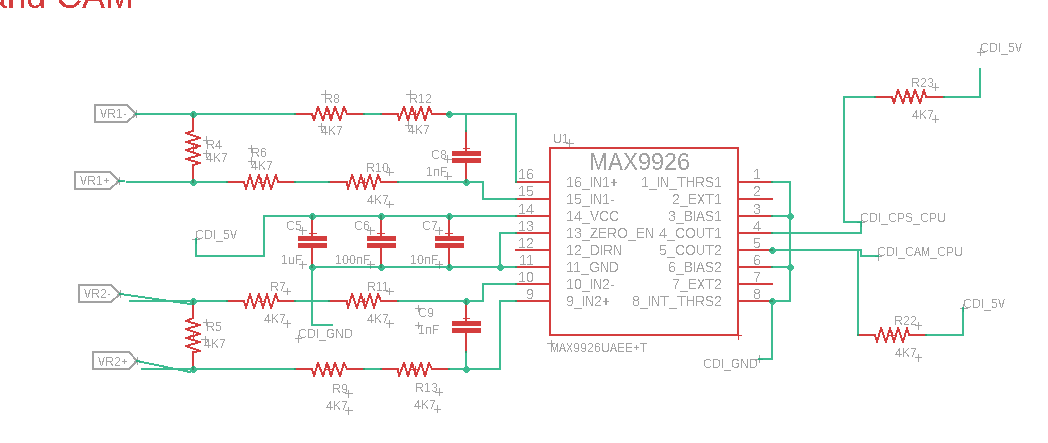
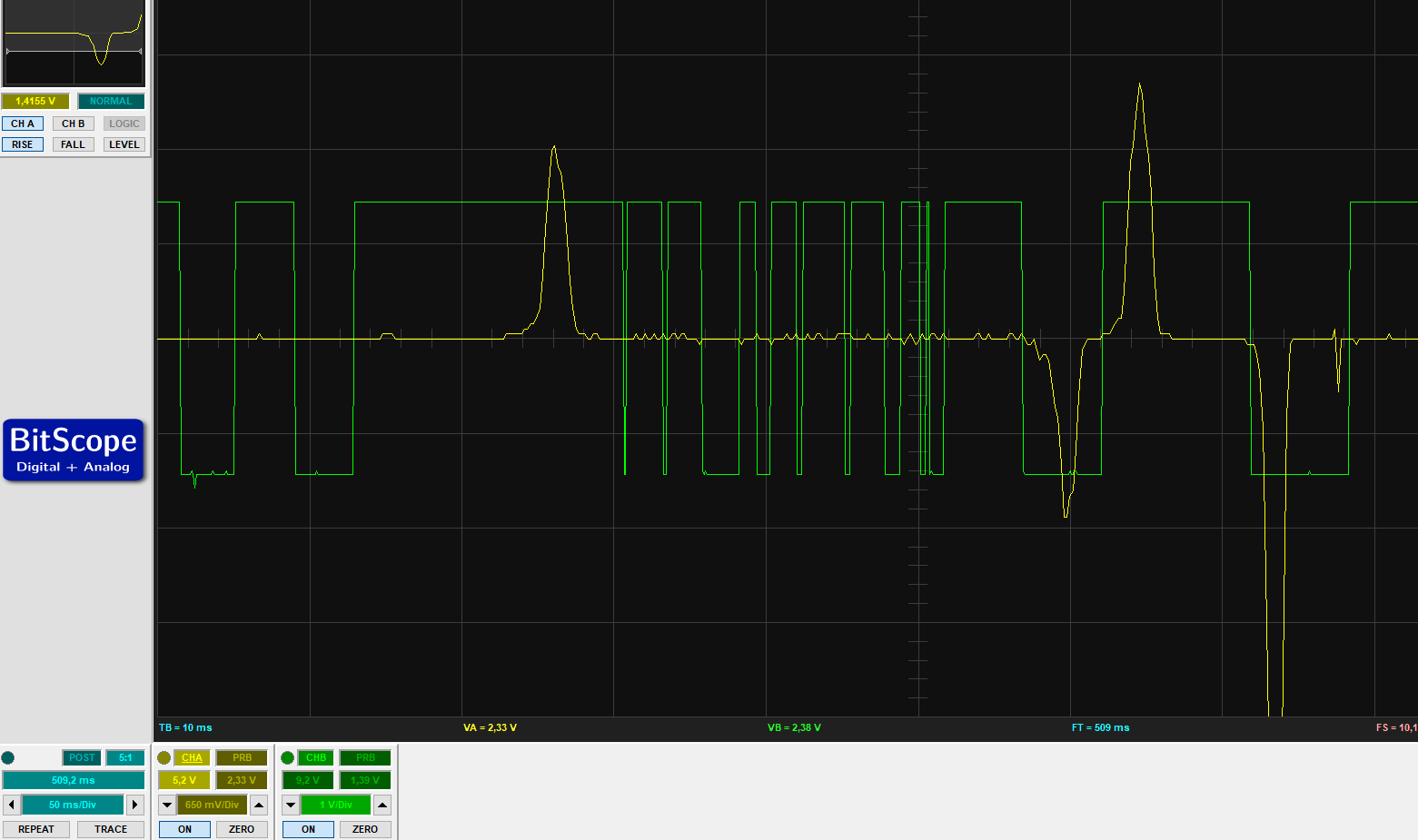
Yellow is VR scope. Green is MAX9926 output.
Re: Another MAX9926 VR board
Posted: Mon May 18, 2020 7:44 am
by Fred
Sorry for the ultra slow approve on your post!
MAX is super sensitive, so if you do have a long period of near zero voltage, it does need to be stable and uniform in direction or you'll get what you got.
I forget the numbers and details around the watchdog timer and don't have time tonight to get into the datasheet again after all this time, but even really slow cranking if it's noise free will result in a good result provided that the zero crossing is natural and where you want it. That is to say that you need to maintain the changing magnetic flux that this sensor style relies on to get a good signal.
If you look at the toyota 4cyl dizzy guts they go to great lengths to make the single shot tooth profile force the magnetic flux change to continue and "place" the zero crossing where they want it at a precise angle.Only on the single tooth where there's a big gap, though, no effort taken on the 24 tooth ring next to it.
Hope that helps!
Re: Another MAX9926 VR board
Posted: Tue May 19, 2020 8:26 am
by Tobbera
Thank you! I ended up adding resistance in series and also lowering the value of the shunt resistor. This made the noise so low the MAX didn't pick it up.
Re: Another MAX9926 VR board
Posted: Sun May 24, 2020 9:11 am
by Fred
Perfect, you can go as low as you like on the shunt, the limit being low speed cranking where the lower you go, the less signal you get, and you could get to the point of preventing starting :-)
Beware of phase offsets that vary with RPM with "softer" circuits, though - you should scope/measure your situation and verify that.
Cheers, Fred.