Modifying Mazda/DSM-type CAS (for the Volvo redblock)

Free Open Source Hardware discussion forum. Post your Free Open Source hardware projects here!
volvoguy
QFP80 - Contributor
Posts: 63
Joined: Sun Jan 22, 2012 10:52 pm
Location: Scotland

Modifying Mazda/DSM-type CAS (for the Volvo redblock)

Post by volvoguy »

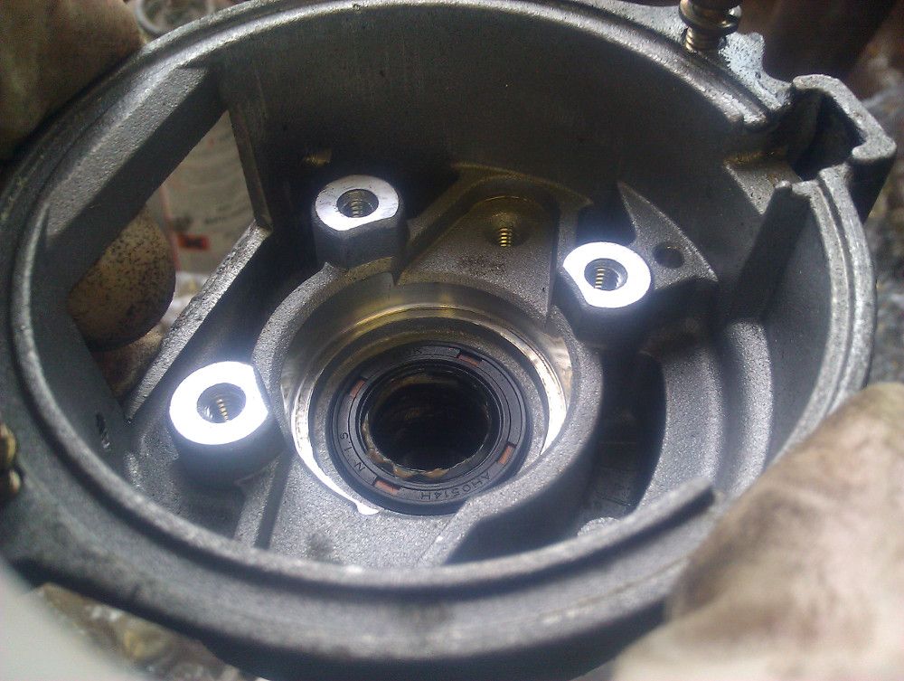
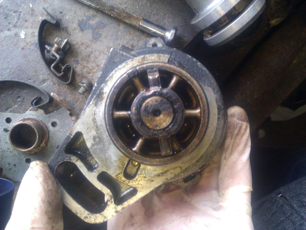
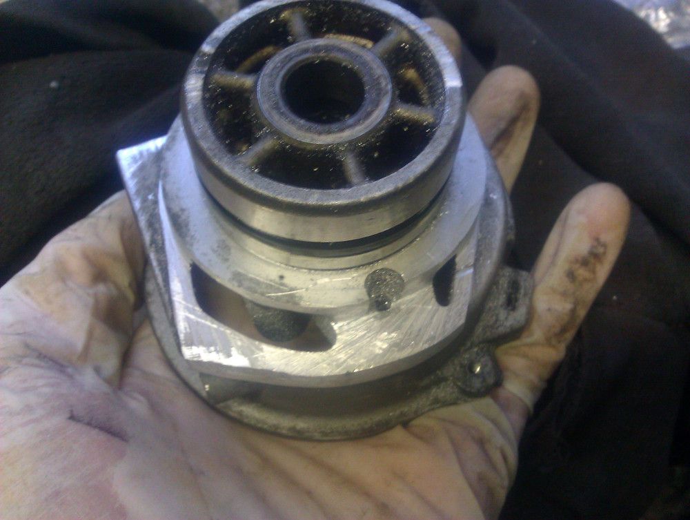
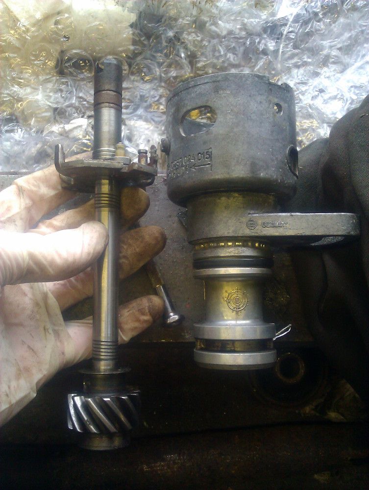
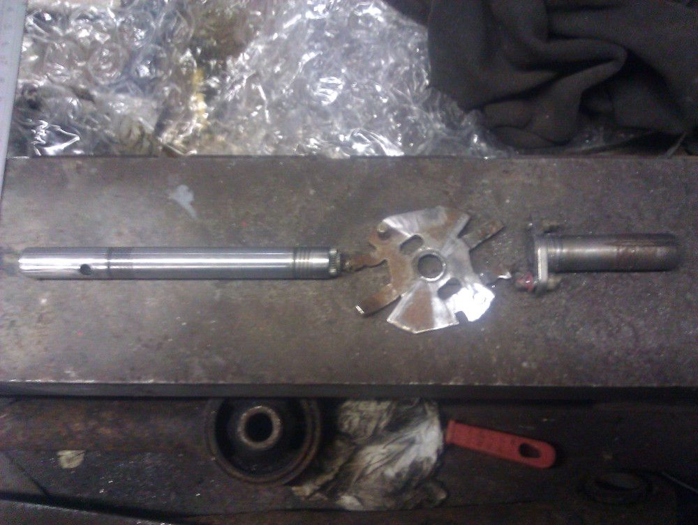
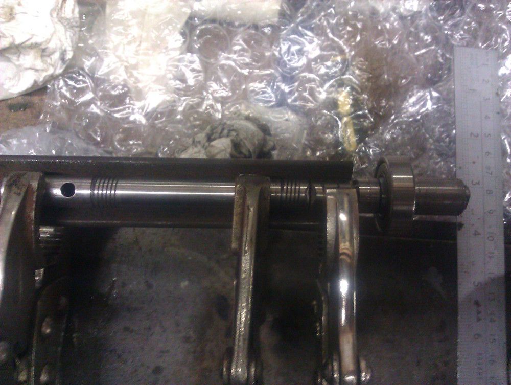
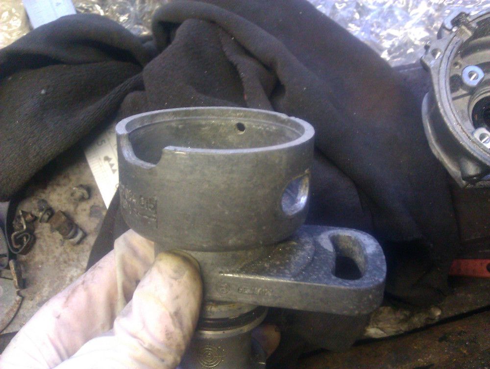
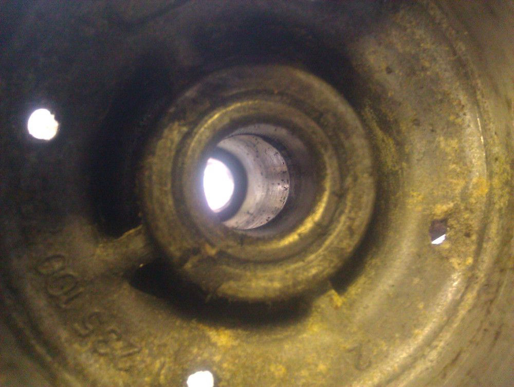
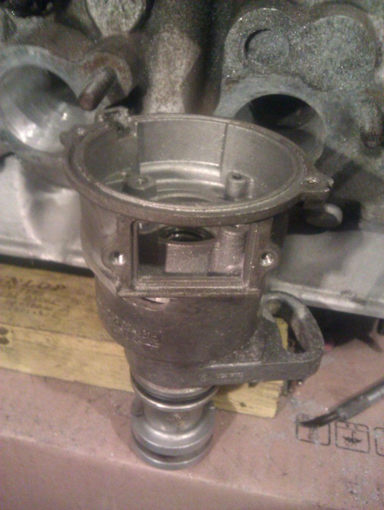
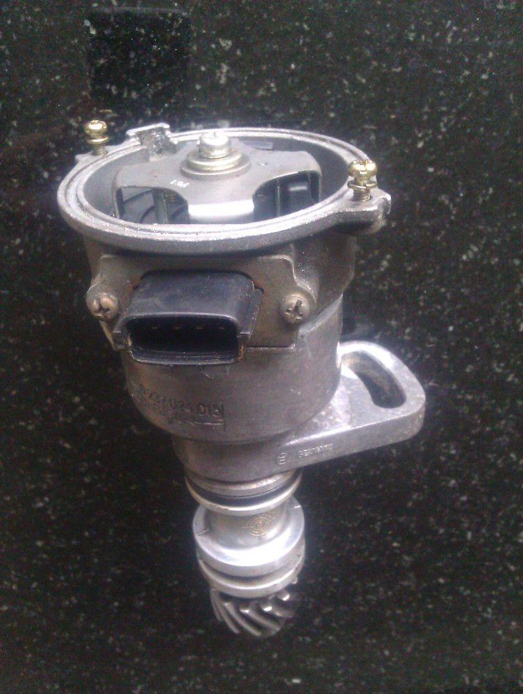
The shaft diameters were sufficiently similar that the bushings in either cast body can be used for either/both shafts. There were two solid sleeve bushings in the LH2.2 Volvo distributor (one at either end, see pics), one in the CAS plus a ball bearing and an oil seal. I was using epoxy, if I was welding them I could have got away with just the CAS body and the lower Volvo bushing, much tidier.

I trimmed both bodies until the CAS slotted into the distributor with the CAS sleeve bushing sitting right on top of the upper Volvo bushing. Cut and welded the shafts, tried to get them coaxial with some extra MIG on the joint and some squeezin's in a 10t press. Used the shaft to align the aluminium bodies while the epoxy cured.

I bookmarked this page but never used it, will probably just solder the pigtail.

I believe the CAS is designed to rotate anticlockwise but the Volvo auxiliary shaft rotates it clockwise so I'll have to invert the 4-2 FreeEMS decoder.

Image
Image
Image
Image
Image
Image
Image
Image
Image
Image
Image
User avatar
Fred
Moderator
Posts: 15431
Joined: Tue Jan 15, 2008 2:31 pm
Location: Home sweet home!
Contact:

Re: Modifying Mazda/DSM-type CAS (for the Volvo redblock)

Post by Fred »

I've never tested the hall type, though I actually have one here. I'm not sure if it's 4/1 or 4/2, though. In either/both cases, the angles may be different than the optical one (very likely). So they'll have to be tuned/a variant provided for that anyway.

Rather than inverting it, you could re-index the two pieces relative to each other such that it works normally again. Up to you, an "invert decoder" patch is a very easy patch to maintain and rebase going forward, however you'll NEVER be able to grab the binary from the server and just use it, which sucks for various reasons and will always suck a bit.

The upshot of both of the above is that if you do re-index I won't be able to use your results as a reference because we won't know what the reference is supposed to look like.

Neat job for tigless! :-)
DIYEFI.org - where Open Source means Open Source, and Free means Freedom
FreeEMS.org - the open source engine management system
FreeEMS dev diary and its comments thread and my turbo truck!
n00bs, do NOT PM or email tech questions! Use the forum!
The ever growing list of FreeEMS success stories!
User avatar
masterkorp
LQFP112 - Up with the play
Posts: 171
Joined: Tue Jan 17, 2012 11:21 am
Location: Ponte de Lima, Portugal

Re: Modifying Mazda/DSM-type CAS (for the Volvo redblock)

Post by masterkorp »

Interesting !

A nice method to get engine position, keep up the work.
I may use this for my kadett in the long run.
ivan141
LQFP112 - Up with the play
Posts: 148
Joined: Sat Sep 29, 2012 9:16 pm
Location: Rotterdam, the Netherlands

Re: Modifying Mazda/DSM-type CAS (for the Volvo redblock)

Post by ivan141 »

I get the feeling a couple of steps arent pictured, but maybe it's better to have the parts in hand while looking at this.
Looks like you welded the bottom of the volvo dizzy shaft to the top of the mazda/mitsu shaft, cut the distributor top off and glued the CAS on in place, correct? You make it sound a bit easier than the yoshifab guys do, but they're selling the conversion so that's hardly surprising.

Technically I think this should be a better solution than a crank wheel, is there any need for a second trigger wheel (flywheel pattern) with this in place?
FABRICA MI DIEM, PVNC!
User avatar
Fred
Moderator
Posts: 15431
Joined: Tue Jan 15, 2008 2:31 pm
Location: Home sweet home!
Contact:

Re: Modifying Mazda/DSM-type CAS (for the Volvo redblock)

Post by Fred »

Josh is a super nice guy, and his parts are nicely designed and made. He makes only a modest living from his business, so I'd support him any time I could. That said, I'm all for DIY too :-)

A cam-driven CAS is not a technically better solution than a crank + sync for accuracy reasons. It is, however, very convenient. And no, you don't need a crank wheel with it at all.

My truck engine (fwd sourced) has this CAS dead stock and I manage to make a lot of power with that just fine.

Fred.
DIYEFI.org - where Open Source means Open Source, and Free means Freedom
FreeEMS.org - the open source engine management system
FreeEMS dev diary and its comments thread and my turbo truck!
n00bs, do NOT PM or email tech questions! Use the forum!
The ever growing list of FreeEMS success stories!
volvoguy
QFP80 - Contributor
Posts: 63
Joined: Sun Jan 22, 2012 10:52 pm
Location: Scotland

Re: Modifying Mazda/DSM-type CAS (for the Volvo redblock)

Post by volvoguy »

ivan141 wrote:I get the feeling a couple of steps arent pictured
More of an overview of modifying the CAS than a list of specific steps that can be followed to get it into a Volvo, yes. There's no way I could really give dimensions for any of it, apart from getting the shafts aligned it's all pretty baggy-tolerance, 'keep cutting it until it fits' work.
ivan141 wrote:Looks like you welded the bottom of the volvo dizzy shaft to the top of the mazda/mitsu shaft, cut the distributor top off and glued the CAS on in place, correct?
Yep, that was this bit:
volvoguy wrote:I trimmed both bodies until the CAS slotted into the distributor with the CAS sleeve bushing sitting right on top of the upper Volvo bushing. Cut and welded the shafts [...] Used the shaft to align the aluminium bodies while the epoxy cured.
The only picture I took of the shafts was the two sections clamped into a section of angle-iron ready to be welded, seventh picture down from the top.
ivan141 wrote:You make it sound a bit easier than the yoshifab guys do, but they're selling the conversion so that's hardly surprising.
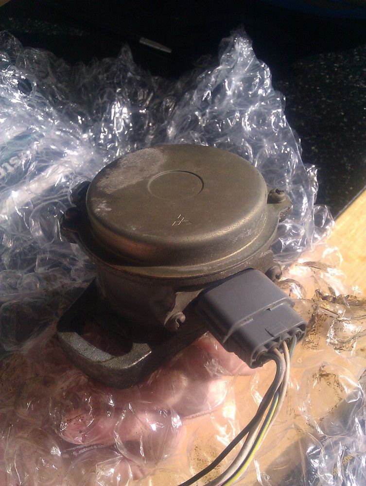
I don't know how easy Josh says this is, it's certainly nowhere near as easy or neat as the yoshifab adapter. I had more time than money when I did it though, and the >$200 + international postage + 20% VAT looked too strong when the distributor was free and the CAS was about $15.
ivan141
LQFP112 - Up with the play
Posts: 148
Joined: Sat Sep 29, 2012 9:16 pm
Location: Rotterdam, the Netherlands

Re: Modifying Mazda/DSM-type CAS (for the Volvo redblock)

Post by ivan141 »

Lets just say that the way you put it makes me think I can get this done without any milling work required, which is one thing I cant do myself, and getting my machinist friend to do it is getting increasingly tough, seems like no one is allowed to do much hobbying between work anymore these days.

I'm not trying to slam yoshifab, but I am not by any means a rich man, so I need to save money where I can.. Costs add up fast when building up an engine. A scrap volvo dizzy and mazda CAS are easy to source cheap.. cutting and welding is something I can do myself. If that saves me 200 euro's, then that is a HUGE amount of funds saved.

I like the idea of gluing the parts together. A friend of mine used industrial glue to hold a torn rubber engine mount together (lacking new part availability), and it has held out for over a year and is still going strong.. sounds like it should work fine for metals as well.
FABRICA MI DIEM, PVNC!
volvoguy
QFP80 - Contributor
Posts: 63
Joined: Sun Jan 22, 2012 10:52 pm
Location: Scotland

Re: Modifying Mazda/DSM-type CAS (for the Volvo redblock)

Post by volvoguy »

No milling, no, just a hacksaw and file. That's the advantage of using the shaft running between the three bushings to locate the distributor and CAS body, and gluing them. Instead of needing a precise fit between the two housings to weld them, you apply the epoxy and just wiggle and turn the shaft to position the bodies so the shaft doesn't bind.

Welding the shafts is the trickiest part. If you have a dial indicator then you're fine. If not, and you use all three bushings, you could minimally file the shaft where it contacts the top two. That would leave the bottom Volvo bushing and the ball bearing in the CAS body which would probably minimise the negative effects of the wobble. I suppose another way would be to leave the shafts separate and weld a "keyhole" shape onto the Volvo shaft that the key on the CAS shaft could fit into.
ivan141
LQFP112 - Up with the play
Posts: 148
Joined: Sat Sep 29, 2012 9:16 pm
Location: Rotterdam, the Netherlands

Re: Modifying Mazda/DSM-type CAS (for the Volvo redblock)

Post by ivan141 »

I just came across this solution, would something like this work in combination with the 44-2-2 flywheel?
Image
Image
Image
(pictures are just remote linked, but they give the general idea).

Weld a single tooth cam trigger to the cam pulley, and mount a sensor to the valve cover.
Looks quite elegant in it's simplicity (and can be accomplished even cheaper than I can find a fitting CAS over here).
FABRICA MI DIEM, PVNC!
volvoguy
QFP80 - Contributor
Posts: 63
Joined: Sun Jan 22, 2012 10:52 pm
Location: Scotland

Re: Modifying Mazda/DSM-type CAS (for the Volvo redblock)

Post by volvoguy »

I don't see why it shouldn't work. You could use more than one tab on the cam wheel for faster positioning. If you're thinking about getting a better flywheel you could also count all 38 teeth on the auxiliary wheel for resolution. It's cheaper to replace the flywheel if you're not limited to something with 60-2 timing.
Post Reply