I'm working on a layout right now and am really struggling with how to mount the fets.
I'm at something like 12 between injectors/boost/idleair/etc.
I started out with surface mount, but I'm starting to think that's too much of a pain in the bottom and also worried about PCB disipating all the heat, and running out of room.
But I'm also concerned with heatsinking if I go with a TO-220 package. The current MS case that I was trying to fit this all into is lacking in surfaces to use, and I'm hesitant to start bolting things to the top or bottom panels because it's nice to be able to get at both sides of the board quickly.
So any ideas would be great!
Design Considerations for FET mounting
-
GartnerProspect
- LQFP112 - Up with the play
- Posts: 160
- Joined: Tue Apr 08, 2008 9:14 pm

Re: Design Considerations for FET mounting
DPAK + adhesive heatsinks
OR
FETs shouldn't get very warm if you keep them in the on OR off positions. They only put out significant heat when switching. Hence, it's important to A switch fast, or B switch infrequently, or both.
OR
FETs shouldn't get very warm if you keep them in the on OR off positions. They only put out significant heat when switching. Hence, it's important to A switch fast, or B switch infrequently, or both.
DIYEFI.org - where Open Source means Open Source, and Free means Freedom
FreeEMS.org - the open source engine management system
FreeEMS dev diary and its comments thread and my turbo truck!
n00bs, do NOT PM or email tech questions! Use the forum!
The ever growing list of FreeEMS success stories!
FreeEMS.org - the open source engine management system
FreeEMS dev diary and its comments thread and my turbo truck!
n00bs, do NOT PM or email tech questions! Use the forum!
The ever growing list of FreeEMS success stories!
-
GartnerProspect
- LQFP112 - Up with the play
- Posts: 160
- Joined: Tue Apr 08, 2008 9:14 pm
Re: Design Considerations for FET mounting
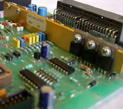
You make a good point. I like the simple long bar. I had envisioned something similar but had concerns about physical stress on the packages. Most heatsinks I see in production peices are attached to the board. Can't tell if that one is or not.
But I like it. I also didn't think of putting the fets back to back. That probably stiffens that up nicely and definitely makes for a compact package.
But I like it. I also didn't think of putting the fets back to back. That probably stiffens that up nicely and definitely makes for a compact package.
Re: Design Considerations for FET mounting
I'm pretty sure that isn't attached to the board. It is light ally though, so wouldn't put a lot of stress on back to back stuff with greater than 3 through hole mounting spots. On the average the power dissipation should be enough provided that only a proportion of devices are actually generating significant heat. That is a Miata Link ECU (an early one) with a single sided board. They work. I think it goes a long way to showing what can be done with a single layer board and basic setup. I think we can do better without going nuts with board fanciness :-)
DIYEFI.org - where Open Source means Open Source, and Free means Freedom
FreeEMS.org - the open source engine management system
FreeEMS dev diary and its comments thread and my turbo truck!
n00bs, do NOT PM or email tech questions! Use the forum!
The ever growing list of FreeEMS success stories!
FreeEMS.org - the open source engine management system
FreeEMS dev diary and its comments thread and my turbo truck!
n00bs, do NOT PM or email tech questions! Use the forum!
The ever growing list of FreeEMS success stories!
-
slacker.cam
- QFP80 - Contributor
- Posts: 69
- Joined: Sun Jan 27, 2008 10:25 pm
Re: Design Considerations for FET mounting
What kind of board are you designing?
Surface mount FETs will be fine IMO, thats just a vibe though, no calcs done. A surface mount fet with adequate vias to the ground plane will be sufficient for the amount of current that we are switching. None of our parts draw that much current and if you get a fet with a half decent Rds on then the heat dissipation should be very low. Using a FET driver is relatively mandatory unless we can get fancy ones with ttl inputs. Adhesive heatsinks gives me the willys big time, thats not an engineered solution, its a patch on a problem rather than a fix...
Surface mount FETs will be fine IMO, thats just a vibe though, no calcs done. A surface mount fet with adequate vias to the ground plane will be sufficient for the amount of current that we are switching. None of our parts draw that much current and if you get a fet with a half decent Rds on then the heat dissipation should be very low. Using a FET driver is relatively mandatory unless we can get fancy ones with ttl inputs. Adhesive heatsinks gives me the willys big time, thats not an engineered solution, its a patch on a problem rather than a fix...
Re: Design Considerations for FET mounting
AFAIK all the self protected ones (which is all i would consider for this, given the types that might end up using it) have ttl inputs. Could be wrong though. Is the FET driver still required at such low switching frequencies? I suspect not.
DIYEFI.org - where Open Source means Open Source, and Free means Freedom
FreeEMS.org - the open source engine management system
FreeEMS dev diary and its comments thread and my turbo truck!
n00bs, do NOT PM or email tech questions! Use the forum!
The ever growing list of FreeEMS success stories!
FreeEMS.org - the open source engine management system
FreeEMS dev diary and its comments thread and my turbo truck!
n00bs, do NOT PM or email tech questions! Use the forum!
The ever growing list of FreeEMS success stories!
-
GartnerProspect
- LQFP112 - Up with the play
- Posts: 160
- Joined: Tue Apr 08, 2008 9:14 pm
Re: Design Considerations for FET mounting
What I'm doing is designing a development board for my own personal side project. It's going to be an all inclusive platform with 8 injector drivers, all the things we've come to expect like boost control, water injection, 8 ignition outputs, etc. But the CPU is going to be on an expansion board which will make the design flexible for me testing different things without reinventing the wheel every time.
For example, I want to start with a MS cpu for base hardware testing and then ease myself into something more advanced. I don't like to put all my eggs in one basket so to speak and I have a lot of seat time on the MS right now.
The injector fets I've been looking at are the VND5N07, which seems to be a popular choice. I haven't seen any major problems with these... except they don't seem to be availible in 220 package yet. But the part it replaces, the VNP5N07FI is, in limited quantities.
I was leaning towards the 220 package because I think it's more DIY friendly, increases free-space on the board, and I'd worry less about power dissipation. But I'm not opposed to D-pak, and in some cases would prefer. With 12 of them things might get a little tight, that can be delt with. I was trying to keep the total foot print to the 4"x6" frame since those are the cases I have at my disposal. But I'm willing to expand if I have to as well. After setup, PCB real estate really doesn't cost much I'm finding.
I'm going to spend some time tonight looking at the expected dissipation of the fets in worst-case scenario and see what kind of wattage I'm working with...